Read post # 14 again DONT POWER THE BUGGER UP! Every time you power it up without doing a thorough check first you'll damage more and more components making it uneconomic to fix.
First you need to check you haven't got a short.
1) Do a thorough visual inspection of every board,every solder/cable joint & every component with a magnifying glass. Your looking for burnt scorched or cracked damaged components.
2) Get a DMM, set to ohms, black lead to ground/chassis, red lead to big power supply caps or PSU OP, if you get less than 100r especially if it's a few ohms or less, you need to trace that short. Which means...
3) Go through every Q (transistor) and diode and do a quick continuity check, just pop your probes across leads, if you get a beep,it's a possible dead Q or diode. While your at all this you should be analysing the circuit, getting a feel for what does what.
4) Same process for every cap. Every cap needs checking for leakage both physical and electrical.
5) Only when your 100% sure all is ok do you apply power, not to everything at once, first power the power supply up on it's own on a lamp limiter.
6) When that's ok plug in each board one at a time, your still on the lamp limiter, even better test each PCB or board or a current limited bench power supply.
7) Lastly when you've replaced a component, check, recheck and check again your work. Don't re-cap the whole mixer, do one board at a time, check,power up and test,then onto the next board.
Hope that helps, Andy.
my go to is my Fluke meter set on Diode function...and seeing as how you've asked this may help https://www.electricalengineering.xyz/article/how-to-test-a-bjt-transistor-using-digital-multimeter/
and this should be the general configuration of what your looking at

and this should be the general configuration of what your looking at
I just powered it up the one time, it sounded like I did again upon reading it back but it was just the once. But yes I am building a current limiter/dim bulb tester for when I power it up next time.Read post # 14 again DONT POWER THE BUGGER UP! Every time you power it up without doing a thorough check first you'll damage more and more components making it uneconomic to fix.
First you need to check you haven't got a short.
1) Do a thorough visual inspection of every board,every solder/cable joint & every component with a magnifying glass. Your looking for burnt scorched or cracked damaged components.
2) Get a DMM, set to ohms, black lead to ground/chassis, red lead to big power supply caps or PSU OP, if you get less than 100r especially if it's a few ohms or less, you need to trace that short. Which means...
3) Go through every Q (transistor) and diode and do a quick continuity check, just pop your probes across leads, if you get a beep,it's a possible dead Q or diode. While your at all this you should be analysing the circuit, getting a feel for what does what.
4) Same process for every cap. Every cap needs checking for leakage both physical and electrical.
5) Only when your 100% sure all is ok do you apply power, not to everything at once, first power the power supply up on it's own on a lamp limiter.
6) When that's ok plug in each board one at a time, your still on the lamp limiter, even better test each PCB or board or a current limited bench power supply.
7) Lastly when you've replaced a component, check, recheck and check again your work. Don't re-cap the whole mixer, do one board at a time, check,power up and test,then onto the next board.
Hope that helps, Andy.
Thank you for these steps, helps me quite a bit actually. Very much appreciated.
-B
any developments?
as to testing the transistors start here, and although the transistor type is different the same applies to the TO-3's in your console
as to testing the transistors start here, and although the transistor type is different the same applies to the TO-3's in your console
I found that 2 of the (4) power transistors had shorts but the other two checked out ok on the multimeter. I was under the impression that if one of them failed, it is likely they all have failed but now I'm not 100% since 2 are showing to be ok when testing with the multimeter. Is there a chance that 2 of them did not fail? Sorry I should probably know this, thank you very much for your help. Much appreciatedso any chance that you've located what's pulling the extra current??
entirely possible, but due to the fact that these are the pass transistors for the power supply regulators i would replace them all.
there has to a gross fault somewhere in the circuitry of this console to cause these to fail, it could be anything from channel faults pulling additional current to the now quite old supply filter caps being the culprits. it's going to take lots of searching to suss out.
have you gotten schematics for this as of yet?
I'm not even sure that there is one, this was a custom built power supply (tmk the original ones were somewhat insufficient).entirely possible, but due to the fact that these are the pass transistors for the power supply regulators i would replace them all.
there has to a gross fault somewhere in the circuitry of this console to cause these to fail, it could be anything from channel faults pulling additional current to the now quite old supply filter caps being the culprits. it's going to take lots of searching to suss out.
have you gotten schematics for this as of yet?
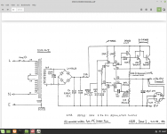
Linear regulated power supply's are pretty simple and likely to be either built around something like a uA723 IC, see attached, in which case a look at the IC's datasheet and application note should give you a good idea of what's going on, or there'll be an opamp and a few transistors. This is broadly speaking.
Things to look out for check as well as the obvious series pass tranny's is the opamp or reg IC, I'll pull em out and fit a DIP socket to allow easy checking etc. Also check zeners, diodes and any voltage reference. Other than that is to power the supply up on a current limited supply with only one series pass device fitted. Get that running without smoke and your laughing.
Andy.
Attachments
well yes identifying what's used as an error amp in the supply is going to tell us if the supply is original or a subsequent replacement/ upgrade the originals where zener based and went south fast when outboard gear of dubious manufacture ( and grounding ) where interfaced with the console.
it may not seem worth it but the schematic will go a long way in helping you flesh this out....is 50 bucks for the Pdf not worth it?
otherwise it's a lot of reverse engineering to come up with a total current draw to create a supply regulator that going to handle what this thing is going to need.
it may not seem worth it but the schematic will go a long way in helping you flesh this out....is 50 bucks for the Pdf not worth it?
otherwise it's a lot of reverse engineering to come up with a total current draw to create a supply regulator that going to handle what this thing is going to need.
You/we NEED the schematic to begin with; an experienced Tech may do without, but then his minimum bench fee will be higher than U$50, so ...
But search around, specially Trident fan Forums, somebody will probably chime in, upload it, whatever.
Besides using a dim bulb limiter, start testing your supply WITHOUT A LOAD.
FIRST we get ´+/-17V, +48V, whatever, UNLOADED; if you wish load the lower voltage ones with 1k or even 220 ohm 5W and +48V with, say, 10k 1W just to make it "work" something, but DEFINITELY NOT THE MAIN MIXER.
- Home
- Amplifiers
- Power Supplies
- Power Transistor Identification help