Hi all,
I want to change the outputs for this amp which are IRFB31N20D. But these are discontinued. I am having few same type amps with these outputs to fix. I would like to know if anybody had substituted with any other MOSFETs successfully. Thanj you.
I want to change the outputs for this amp which are IRFB31N20D. But these are discontinued. I am having few same type amps with these outputs to fix. I would like to know if anybody had substituted with any other MOSFETs successfully. Thanj you.
Attachments

What is ccs and how to adjust that.To use the other FETS, an adjustment of the CCS on the driver board may be necessary.
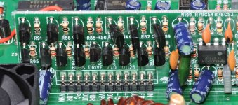
Yes exactly same.Is the component numbering on your board the same as this one?
CCS = Constant Current Source
This is essentially the 'biasing' for the output circuit. Increasing the current through the CCS decreases the deadtime between the two banks of outputs and will make them run hotter as well as pass more current at idle. You will typically need to decrease the CCS current to reduce the idle current through the outputs when something other than the 31N20 is used.
On page 6 of the attached diagram, you'll see R95, a 910 ohm resistor. This is what you'll want to change to change the CCS current. Increasing the resistor decreases the current. You'll typically only need to change it no more than a few hundred ohms. Changing it to 1k may be enough.
Attachments
Hello sir,CCS = Constant Current Source
This is essentially the 'biasing' for the output circuit. Increasing the current through the CCS decreases the deadtime between the two banks of outputs and will make them run hotter as well as pass more current at idle. You will typically need to decrease the CCS current to reduce the idle current through the outputs when something other than the 31N20 is used.
On page 6 of the attached diagram, you'll see R95, a 910 ohm resistor. This is what you'll want to change to change the CCS current. Increasing the resistor decreases the current. You'll typically only need to change it no more than a few hundred ohms. Changing it to 1k may be enough.
The amp is trying to boot several times before it finally comes on. I have checked soft start capacitor and it was good.
No not using any current limit. After it powers up it stays at 1.2amps. Everything's works good. I found when I remove Q8 amp comes on very good. All the parts around q8 looked good.Is the 12v supply too limited on current?
What's the idle current after is finally powers up?
I used black probe on secondary ground and while the amp trying to come on, the voltages keep jumping so I dont know whats the exact voltage. But after it comes on it was around -53v on pin3, -52.4v on pin2 and output was -52v that is pin 1.That's over-current protection.
What's the reference voltage on the over-current comparator?
That's referenced to the negative rail.
Measure from pin 4 (black probe) to pin 2 on the comparator. The voltage should be very stable.
Measure from pin 4 (black probe) to pin 2 on the comparator. The voltage should be very stable.
Pin4 to pin2 i have 0.230vThat's referenced to the negative rail.
Measure from pin 4 (black probe) to pin 2 on the comparator. The voltage should be very stable.
Pin3 is 0v
Post the DC voltage on all terminals of that IC, black on pin 4. Copy and paste the following list and fill in the blanks.
Pin 1:
Pin 2:
Pin 3:
Pin 4: black
Pin 5:
Pin 6:
Pin 7:
Pin 8:
Pin 1:
Pin 2:
Pin 3:
Pin 4: black
Pin 5:
Pin 6:
Pin 7:
Pin 8:
Pin 1: 0.117vPost the DC voltage on all terminals of that IC, black on pin 4. Copy and paste the following list and fill in the blanks.
Pin 1:
Pin 2:
Pin 3:
Pin 4: black
Pin 5:
Pin 6:
Pin 7:
Pin 8:
Pin 2: 0.229v
Pin 3: 0v
Pin 4: black
Pin 5: 0.526v
Pin 6: 0.517v
Pin 7: 0v
Pin 8: 15.68v
All these voltages without optocoupler that sends protection out. I did this for the amp to come on.
No R160 is just like diagram 10k. But R71 is 150ohms. And they reading good.Are R160 and R71 the same value as in the diagram?
Are they within tolerance?
Check R161.
The 150 ohm resistor lowers the threshold. I've never seen that value as OEM but I used to change them to 150 ohms to make the protection more sensitive.
The 150 ohm resistor lowers the threshold. I've never seen that value as OEM but I used to change them to 150 ohms to make the protection more sensitive.
R161 is 4.7k and is reading good. So change 150ohms to 220 and try?Check R161.
The 150 ohm resistor lowers the threshold. I've never seen that value as OEM but I used to change them to 150 ohms to make the protection more sensitive.
- Home
- General Interest
- Car Audio
- Boss AR3000D