Another approach is to run the power transistors hot at all times. Then the % change in temperature with music playing will be much lower. This is very wasteful of power, of course, and I'd prefer a more sophisticated approach.
This is necessary, though, when using FETs as their turn-on curves are so shallow relative to BJTs. You typically see FET outputs running at an order of magnitude higher bias than BJTs. You sometimes get BJT designs idling hot but I think this is more due to lazy design, optimizing irrelevant bench measurements or devious marketing.
This is necessary, though, when using FETs as their turn-on curves are so shallow relative to BJTs. You typically see FET outputs running at an order of magnitude higher bias than BJTs. You sometimes get BJT designs idling hot but I think this is more due to lazy design, optimizing irrelevant bench measurements or devious marketing.
How about a somewhat intelligent, soft-starting and look-ahead type of bias control system? That should be possible with integrated, digital audio storage/playback systems. Class AB amplifiers may not even need to operate with optimum bias at all times so perhaps there's a happy compromise where, after a period of low or no signal, bias current can fall to a base level at which distortion isn't particularly noticeable anyway.
Krell did something like this but without the look-ahead (https://www.diyaudio.com/community/threads/krell-i-bias-ideas.294743/post-4785084). That was for keeping the output stage in class A at all times.How about a somewhat intelligent, soft-starting and look-ahead type of bias control system? That should be possible with integrated, digital audio storage/playback systems. Class AB amplifiers may not even need to operate with optimum bias at all times so perhaps there's a happy compromise where, after a period of low or no signal, bias current can fall to a base level at which distortion isn't particularly noticeable anyway.
I suppose you could have a predictive circuit that cranks the bias up in advance of thunderous music. A feed-forward compensation. But it might be easier to apply lots of heat sinking and a thermal feedback circuit.
P.S. What ever happened to "feed-forward"? That was a sexy concept for a while. 🙂
Feed-forward control as in Quad's 405 model?
For anyone unfamiliar with it, Mike Renardson has written an interesting article on his own attempts at working feedforward designs (1998-?) but as far as I know, they have never been commercialised. http://www.renardson-audio.com/classbff.html.
A.M. Sandman's feedforward scheme was probably inspired by Quad's success in the 1970s but IIRC, it was pirated by Japanese interests. I think a plan to use it commercially was stifled in any case. https://www.diyaudio.com/community/attachments/ffec-sandmann-pdf.143419/
https://keith-snook.info/wireless-w...4/Reducing Amplifier Distortion - Sandman.pdf
Technics, the innovative and very successful brand of Matsushita then in the 1970s-80s, produced many modified or rather, dumbed-down variations on the feedforward scheme over many years. The products seem to have been expensive to build and maintain and were eventually reduced to low-cost hybrid modular construction. It really was a sad ending to what began as a milestone in innovative, efficient and popular amplifier design.
Jan Didden is also quite a fan of feedforward systems and if you follow his posts on the topic of Quad's design, he's made some interesting and helpful comments about it here too.
Member
Joined 2009
Paid Member
What gets people excited about Feed Fwd is that it's not Fd bk. But if you read the analysis (paper published by Lipshitz & VanDerkooy) you'll realize that in the Quad, that it's necessary to use negative feedback in order to control the gain and deal with the output network.
In his discussion, Renardson also uses lots of feedback but qualifies it as local rather than global. You could say that's just a technicality but either way, there still needs to be precise or at least stable control of the gain and crossover behaviour. His approach seems to work well enough with local FB but maybe it's still a bit touchy so not yet suitable for consumer products.
I own a Quad or two myself and really like the compact, cool running of their 306 model for home use. It's like class D with decent sound quality in some respects and it has a lively presentation somewhat like PRaT, which vies with the best Naim NAP models I've yet heard, for entertainment value. That's something I would never have expected from Quad's original technology and probably why it's still held in some esteem.
I own a Quad or two myself and really like the compact, cool running of their 306 model for home use. It's like class D with decent sound quality in some respects and it has a lively presentation somewhat like PRaT, which vies with the best Naim NAP models I've yet heard, for entertainment value. That's something I would never have expected from Quad's original technology and probably why it's still held in some esteem.
As far as i can think, output signal distortion profile is somehow dependent on the AC.
There is no such things as " BEST TRANSISTOR"
It all goes with the AC. For example... i had 2 different pairs of TOSHIBA transistors with HUGE DIE's.
One of the pair had super silent and warm sound, with the T38 ferrite on the AC side.
And the other pair of also good TOSHIBA transistors, they sucked... but they didnt. I sucked thinking they were not for audio.
I believe lol, sry its getting more hilarious then i thought it ever could.. but i seriously believe that if i had just changed T38 for a T60 ferrite core at that time... i could have been satisfied with the 2nd pair of Toshiba transistors that i ordered from Estonia.
SO, guys please, tell me about it.
Am i crazy ?
If this is true then we can throw our oscilloscope, measuring units, everything out of the window 🙁 No kidding ....
Last edited:
"the sound quality was awful.. ". What was the most common mistakes about the awful sound? Can you give some hints for control our circuits 🙂Some years ago, I was helping some local schoolkids with checking parts and getting their Ebay kits working, making the bias setting correctly, stable and so on. The case was the last and generally most expensive part they considered (if at all) so some had watched as their builds overheated, burnt or even if everything survived the first power-ups, the sound quality was awful with the board and power supply just lying apart on the desk. They figured something must be wrong with Naim styled kits or blamed the semis because typical emitter-follower designs seemed to work and bias could be adjusted with only a small heatsink or adaptor plate in use for testing.
Schoolteachers didn't seem to understand or even recognize that Naim's QC design was a valid topology either so it came down to doing a demo with references to Rod Elliott's articles on output stage topology at his ESP site. Maybe others here will gain some insight from reading the main article too: https://sound-au.com/articles/cmpd-vs-darl.htm
The most common mistakes are simple wiring errors, especially grounding paths. A ground wire is a long inductor + resistor and one end is not the same connection as the other end. There are grounding strategies like a star wiring, but no set of rules is a substitute for being aware of the ground currents, their magnitudes and waveform. Then there are gross errors like getting parts backwards, and using the wrong resistor etc. Unless you are an expert making a very expensive amplifier, the quality of the parts is not your problem. You cannot spend your way to success, except perhaps by hiring an expert to do it for you.
Rod Elliott's articles on output stage topology discusses some interesting points but it completely misses the most important difference between an 2ef and a cfp, and that is the dynamic performance. A CFP requires a Zobel network and RL build-out, or it is likely to oscillate all by itself, regardless of the global feedback. Of course, the output impedance of the VAS is critical too. And, it is trivial to cross couple a 2ef output. It is not commonly known that it is possible to cross couple a pair of CFPs, but at the cost of PSRR. I cannot exaggerate how common it is for amps to fail due to shoot through current in amps that have no cross coupling. It is very difficult/complicated and ineffective to cross couple a Quasi. Complicated circuits mean slow circuits which means stability problems and artifacts like phase reversal and rail sticking and slew induced distortion.
Rod Elliott's articles on output stage topology discusses some interesting points but it completely misses the most important difference between an 2ef and a cfp, and that is the dynamic performance. A CFP requires a Zobel network and RL build-out, or it is likely to oscillate all by itself, regardless of the global feedback. Of course, the output impedance of the VAS is critical too. And, it is trivial to cross couple a 2ef output. It is not commonly known that it is possible to cross couple a pair of CFPs, but at the cost of PSRR. I cannot exaggerate how common it is for amps to fail due to shoot through current in amps that have no cross coupling. It is very difficult/complicated and ineffective to cross couple a Quasi. Complicated circuits mean slow circuits which means stability problems and artifacts like phase reversal and rail sticking and slew induced distortion.
The point I was making in #4400 was about thermal "feedback" and bias control. Bias can be critical to sound quality as others have said but with Quasi complementary designs, there is always a compromise between the optimal requirements of 2 different output stage topologies connected in series. Measurements and Naim's reputation prove that a happy compromise can and does exist but beginners seldom recognize that you need an enclosure to trap the air and stabilize the bias control for best cost-effective operation.
I've posted the following link several times but it obviously needs repeating for every newbie and those who just don't or won't get it for their own reasons. It's a practical demo of bias requirements for quasi-complementary designs, using a little NAIT2 model for the purpose: http://www.acoustica.org.uk/
Scroll down to "More Naim stuff" and then "bias settings in Naim amplifiers".
Genuine NAP200 models demonstrate a worthwhile improvement on the old basic plan of just placing the Vbe multiplier transistor topside and wherever was convenient on the PCB. As a result, early Naim models had an awfully slow warm-up time, like 20 minutes, so leaving amplifiers on 24/7 became the norm for some owners. Genuine NAP200 product and the early full sized PCB clones, have a considerably shorter thermal path to the Vbe multiplier which means the amp is up and running well enough after only a few minutes and this was a considerable improvement. As said though, this particular kit of parts won't build to anything like its namesake but with attention to a case size appropriate to your available output power, there's no longer any reason for bias control to be any worse.
Expanding on the kids' problem mentioned earlier, I found they were likely to omit expensive, hard-to-get items and use cheap, inappropriate materials like MDF as an open-top surround for their amplifiers, for cost, availability and simply because the internet showed images of what others had done - no matter that they were a bad idea. So now there was virtually no bias control path via the air and it just drifted with the ambient temperature, to some level between useless and hellfire disaster where the sound quality is less than pleasant.
Have anybody tried my first layout i posted here years ago, the same exact layout, diodes,skynet is on the rise trought satellites caps everything the same...maybe its the best if we take electricity in terms of reflections, temperature, grounding and AC.
The environment that is created trought that layout abb a be back may satisfy everyone needs. We just must figure out how we do it with real NAP140 circuit, without additional filtering for super clear sound.
The sound is definitely taken as a whole, diodes in the circuit pay a huge role on "tuning" with the layout and placement of the amplifier, all they need is the powersupply and if they get it we all gonna die, T800 is the scariest one from 1984. We need to make sure everyone gets it... its gonna be hard in near future.
So maybe we could try some additional filter with regulators igbt i gonna be terminator for the front end. Capacitor ESR matters, if done right we can push more sound out of the speaker, especially woman vocals and some other effects.
Last edited:
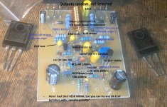
ZTX (VAS) transistors heat the all board. Also power transistors. All PCB temp. is not lower than 30-40C (room tempr. 22C). I believe this is not an accident. I made bias nearly 5mv (for one 0.22ohm). http://www.acoustica.org.uk/ says must be not less than 4.5mv. (make sure your Naim's output stage displays at least 4.5mV across a 0R22 emitter resistor that is, Iq around/up to 20mA..). I think there isno problem about bias and heat of amp.
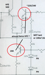
I'm thinking about the transistor's effect in frequency range (or sound qualty) of the amp. I mean is it necessary to find low noise transistors in bc550 or bc239 or is MJE15030/31 or ztx's characteristic (Hfe or others) are important. Do I have to find the true BC550 🙂
I'm thinking about the transistor's effect in frequency range (or sound qualty) of the amp. I mean is it necessary to find low noise transistors in bc550 or bc239 or is MJE15030/31 or ztx's characteristic (Hfe or others) are important. Do I have to find the true BC550 🙂
Last edited:
Okey,
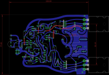
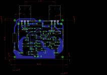
1. Layout of NAP140 or 250 whatever model.
2. Layout for H-140, known as clone.
Both worked well with "TIP 41&42 as drivers.
all the PCBs we need, everythings calculated - trace inductance, reluctance, capacitance, resistance, differentials, everything is in place.
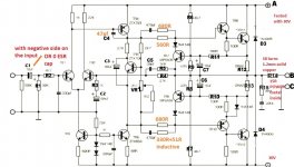
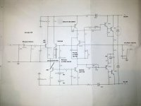
1. NAP250 layout: Most important transistor is VAS, ZTX 653 and 753.
Layout is the key.
2. H-140 layout. good one.
Use only 2 pcb layout drawings.
Next is to build the thing by the layout shown above or super close to it. If we do this it will get us somewhere i think 😛
If we dont follow these concepts, we get stuck i think 😀
1. Layout of NAP140 or 250 whatever model.
2. Layout for H-140, known as clone.
Both worked well with "TIP 41&42 as drivers.
all the PCBs we need, everythings calculated - trace inductance, reluctance, capacitance, resistance, differentials, everything is in place.
1. NAP250 layout: Most important transistor is VAS, ZTX 653 and 753.
Layout is the key.
2. H-140 layout. good one.
Use only 2 pcb layout drawings.
Next is to build the thing by the layout shown above or super close to it. If we do this it will get us somewhere i think 😛
If we dont follow these concepts, we get stuck i think 😀
Attachments
-
 naims.png319.8 KB · Views: 282
 -
 NAP250 schematic.jpg98.4 KB · Views: 307
 -
amp1.pdf41 KB · Views: 144
-
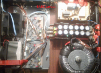
 niam123321.jpg769.2 KB · Views: 257
 -
 naim321123123.jpg756.2 KB · Views: 207
 -
 Untitled.png6.4 MB · Views: 242
 -
 H-140 AUDIO skeem.jpg373.5 KB · Views: 251
 -
 H140 comps.png175.9 KB · Views: 270
 -
h140uus 1p1.pdf78.8 KB · Views: 149
I have tested input transistor types, yes, low noise is a good choice for the first one. But it depends 😀 Basically i think we cant build Amplifiers through the forum... we can but we cant make any statements.... i just dont know what are u talking about and its the same for the opposite person.Do I have to find the true BC550
Maybe with just 2 layouts we can figure it out somehow ?
For example, is it important to find same Hfe power transistors?I have tested input transistor types, yes, low noise is a good choice for the first one. But it depends 😀 Basically i think we cant build Amplifiers through the forum... we can but we cant make any statements.... i just dont know what are u talking about and its the same for the opposite person.
Maybe with just 2 layouts we can figure it out somehow ?
Hmm, atleast to me it seems that using same HFE for 2nd input transistor and CSS is good idea... i have tested it many times, it feels alot cleaner if same HFE is used // but i think it was somehow dependent on my powersupply
There is that "front end" concept too. Its a tricky part... it is temperature, time and ultimately output bias dependent scenario..
Making them equal is cleaner sound but its not just this part of the amplifier, this is a small portion of this tuning... its unknown...
We need Layout... wires, distance, powersupply....
There is no such thing as if something is better or not... ....
But, this NAP250 pcb layout worked quite well... and i dont know why... 😀
Its scary guys 😀 but i love it, it creates a question in ur mind... why it works if it works... and there is no simple answer 😀 makes u think for a longer periods of time, feeling of creativity is born... thinking not thinking at all
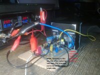
Guys, have anyone tried different voltage lvls on rails ? like 40V on + plus rail and 39.8V on negative rail and vise-versa ...
There is that "front end" concept too. Its a tricky part... it is temperature, time and ultimately output bias dependent scenario..
Making them equal is cleaner sound but its not just this part of the amplifier, this is a small portion of this tuning... its unknown...
We need Layout... wires, distance, powersupply....
There is no such thing as if something is better or not... ....
But, this NAP250 pcb layout worked quite well... and i dont know why... 😀
Its scary guys 😀 but i love it, it creates a question in ur mind... why it works if it works... and there is no simple answer 😀 makes u think for a longer periods of time, feeling of creativity is born... thinking not thinking at all
Guys, have anyone tried different voltage lvls on rails ? like 40V on + plus rail and 39.8V on negative rail and vise-versa ...
Attachments
Last edited:
I came to a conclusion that nothing matters... absolutely nothing, there is just no point on discussing anything that concerns analog equipment sound. It does not make sense to me anymore. Its a thing where every screw can make a big difference.
This scheme can be configured in multiple ways... its like liquid, never stays in place, always moving... it feels like its from starwars or stargate equipment that was left behind here on earth lol 😀
There is just no point... something that is better for me is worse for you and vise versa. Where is that circuit from 😀
But i think i understand a little bit more to be sure what i am talking about.... those harmonics and artefacts, they are not just generated by something alone... its a so closed loop system... and amplifier will benefit from harmonics and some impedance characteristics coming from the psu, wires or whatever environment.
Its a wonderful peace of a equipment lol 😀 The best part is that it is very hard to produce it for profit which makes it ideal imo. So hard to make 2 amplifiers sound the same...
Circuits that cant be build based on cash, money or power... this is the one.
Last edited:
- Home
- Amplifiers
- Solid State
- NAP-140 Clone Amp Kit on eBay