I tried hard but didn't get past the crackling noise. With probes at the TDA1541 the timing looks decent, see attached screen shot. BTW I had XTI@PMD100 = 256fs and BCKI@PMD100 = 64fs. With XTI@PMD100 = 384fs I still get BCKO = 256fs at the scope (I hoped for 192fs). Running the PMD100 in 4x oversampling mode (the latter requires program mode, but I am fine with that) would still result in BCKO being 256fs. So that would only help with additional glue logic which reduces the speed of the transmission between PMD100 and TDA1541: any hints about that...?
Attachments

You cannot clock 20 bits into the TDA1541.
and use complementary offset binary
I had succes today with DF1700 running 8xOS on TDA1541 and tda1541A in Sim_mode
https://www.bramjacobse.nl/wordpress/?p=8972
and use complementary offset binary
I had succes today with DF1700 running 8xOS on TDA1541 and tda1541A in Sim_mode
https://www.bramjacobse.nl/wordpress/?p=8972
Last edited:
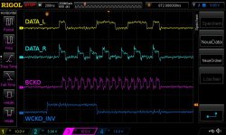
I used inverted WCKO as LE in this screen shot, but also tried various circuits with flip flops. How did you create LE?
BTW I ordered your SPDIF and LED boards from Ebay a week ago for my CD303 🙂
Maybe my TDA1541A is a bit damaged, because I took it from an Arcam Delta Black Box 1 where it was powered from +5V / -15V / -6V (instead of -5V) for decades...?
BTW I ordered your SPDIF and LED boards from Ebay a week ago for my CD303 🙂
Maybe my TDA1541A is a bit damaged, because I took it from an Arcam Delta Black Box 1 where it was powered from +5V / -15V / -6V (instead of -5V) for decades...?
Last edited:
Latch just before the new word is clock in the DAC, Its the Deglitch Control clock from the DF1700
Audio_L&R Data format = complementary offset binary
The DF1700 puts out Data word of 20 bits long , only the first 16 are used ( clock in the DAC )
And I inverted bit clock,
I will try to delay the latch 1 clock cycle . later this week.

BTW the Display and spdif boards are not mine..🙂
Audio_L&R Data format = complementary offset binary
The DF1700 puts out Data word of 20 bits long , only the first 16 are used ( clock in the DAC )
And I inverted bit clock,
I will try to delay the latch 1 clock cycle . later this week.
BTW the Display and spdif boards are not mine..🙂
Last edited:
Yes, I also used COB from the PMD100. I will try to get another TDA1541, maybe mine is damaged. Inverting the deglitch clock from the DF1700 should work as well: you would have the rising edge of latch after a stopped clock period, this could even sound better. I delayed my DATA lines in order to place them over the falling edge of BCK with flip flops as shown here. Same method can be used to delay LE: that would even provide a reclocked LE...
Last edited:
I'm not sure if the DAC latch on the rising or faling edge 🤔.
i'm listening to 16 or 15 bits audio ?
i'm listening to 16 or 15 bits audio ?

Left justified (not i2s), MSB first, MCLK = 256x, BCK = 64x
The PMD100 always outputs BCK= 256x regardless of the settings for input and output as far as I can tell. If your DF1700 configuration works it means that PMD100 should also work, right...?
The PMD100 always outputs BCK= 256x regardless of the settings for input and output as far as I can tell. If your DF1700 configuration works it means that PMD100 should also work, right...?
I used a CM6631 based USB device (and divided BCK as the CM outputs only 128x), next thing I will try is SPDIF via DIR9001...
You cannot just divide bclk and expect things to work. You've broken the relationship between clock and data.
Thanks for pointing this out: I checked again the settings of the CM6631 and indeed it can output BCK = 64x - I tried without divider and same result: only crackling noise...
- Home
- Source & Line
- Digital Line Level
- PMD100 to TDA1541 in smultaneous mode