Wow look at the discussion since I last posted. Actually its very intersting that there are so many factors to consider. Baffle Width is locked in for me and maybe c to c spacing as well. I will attach images of my design so far. I'm sure there are many things which could be tweaked done differently.
Attachments
The above post is about the bass driver. This 15 inch pro Driver is rated at about 98db 1W 1 m, but after it is installed and DSP applied, it will probably be around a natural 95db. I honestly think I won't use more than 50 Watts ever into this driver. (still waiting on its arrival) https://faitalpro.com/en/products/LF_Loudspeakers/product_details/index.php?id=151060100 Meanwhle I have been busy
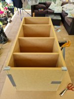
building the enclosure. I know you can't really see the design from these pics. I will post a design sketch next
building the enclosure. I know you can't really see the design from these pics. I will post a design sketch next
Attachments


Haha sorry for spoiling your topic but anyway I think I will get myself a pair of 15fh520 in something like 100l...
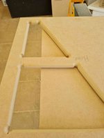
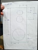
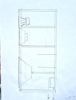
Some of my plans here. There is a drawing depicting the horizontal braces and port placment. The midrange box will be between the two upper braces. it has an angled back wall to minimise resonances. The woofer I have put very low down to minimize floor bounce and maximise bass spl.
The 8 inch mid driver is off center by about 1/5 of the baffle width. I simulated it on basta diffraction software and this seemed to look the best. I am also thinking of making the front baffle thicker so I can put a larger radius round over on the edges. what do you all think?
The 8 inch mid driver is off center by about 1/5 of the baffle width. I simulated it on basta diffraction software and this seemed to look the best. I am also thinking of making the front baffle thicker so I can put a larger radius round over on the edges. what do you all think?
Attachments


I looked at that too but I read somwhere that that driver the 15FH520 had a Qts that was higher than published specs of 0.39, (think it was around 0.47) meaning that it requires a larger box and will be under damped for a Bass reflex enclosure. lower efficiency slightly as well, but it does have the demodulation ring !Haha sorry for spoiling your topic but anyway I think I will get myself a pair of 15fh520 in something like 100l...
Ok I I'll have to investigate...
I can get 15fh500 from Italy for 225€!
Is demodulation efficient below 1khz?
I will use them maximum at 500hz.
15pr400 is well known and doesn't use a demodulation ring neither.
If you have space you could stick a wider front baffle that you could bend...I I'll try this.
Create some grooves parallel to the side on the MDF pannel so you can create an elliptical shape
Hi,Some of my plans here. There is a drawing depicting the horizontal braces and port placment. The midrange box will be between the two upper braces. it has an angled back wall to minimise resonances. The woofer I have put very low down to minimize floor bounce and maximise bass spl.
The 8 inch mid driver is off center by about 1/5 of the baffle width. I simulated it on basta diffraction software and this seemed to look the best. I am also thinking of making the front baffle thicker so I can put a larger radius round over on the edges. what do you all think?
if you checkout path length difference between first floor reflection and direct sound, the bass is not the problem but mid. If transducer is 90cm high, listening height 90cm and listening distance was 3 meters, then the floor bounce has ~50cm longer path length than direct sound and creates interference pattern at listening spot (comb filter), which first dip is around ~340Hz. If you move the transducer closer to floor, the path length difference gets shorter and first dip of resulting comb filter gets higher up in frequency. So, if your bass driver crosses over to mid below say ~200Hz, you could have the bass driver as high as 90cm from the floor without worrying the floor bounce (for the bass) since it would be constructive interference only!
But, remember there is ceiling as well! Now, what is the delay through the ceiling? A lot longer and the dips introduced by ceiling bounce would be much lower, into the bass region and the lower the driver the longer the path through ceiling. Usually the ceiling would perhaps pass some bass through, at least more than a concrete slab floor. Nevertheless, critical thinking before taking stuff to a design!🙂


Anyway, what is the takeaway? Floor bounce is not bass problem it is mid problem! At least the comb filtering resulting from the floor bounce happens at mid frequencies, above ~300Hz. I don't know where the myth with bass / floor bounce originates and I try to post this kind of message whenever I see one. You can have bass driver at any height you like, almost, because the room would probably dominate the sound. Perhaps anything below listening height is just fine. I guess coupling with floor happens when distance is < 1/4wl, which would be ~40cm for ~200Hz, give or take. While you are at it, you could check out what the effect of front wall reflection is, this is serious problem for the bass.
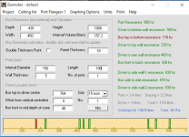
Another thing to consider regarding bass driver height. As the box is so tall, there is gonna be modes within the box that can end up within the bass pass band. Calculator at #61 show there is gonna be below 200Hz. This might, or might not, be a serious problem for the bass. You could, however, put the bass driver mid way of the box height which prevents the lowest mode to happen. There is caveat though, since the top portion of the box has the mid enclosure, horn, convenient space for damping material, what not, the acoustic center of the longest dimension is bit hard to predict and mid way of the baffle might not be mid of the internal path. Anyway, driver at the end of the enclosure would excite the lowest mode the most.
Thus, I suggest you make a prototype box first. Or take the first box as prototype. Measure its performance, and now you have a chance try and fix all issues you spot with it before going full monty and spending for pair only to find out the performance could have been better if prototyped and tweaked a bit 🙂 A prototype will help you to spot and fix multiple issues from construction to measurement, tooling, resonances, bracing, finishing. Basically, you can test your plans and skills to it and if you do it you'll finished speakers will be so much better just because the practice and weed out problems.
Have fun!😀
Last edited:
Here is an interesting link, a guy made speakers with XT1664 horn and 18Sound NSD1480N, Faitalpro 15FH500
https://www.audiosciencereview.com/forum/index.php?threads/big-2-way-cardoid.20728/
https://www.audiosciencereview.com/forum/index.php?threads/big-2-way-cardoid.20728/
What about, if crossing around the first floor bounce dip frequency and steering the crossover dip towards the reflection point? 🤔Hi,
if you checkout path length difference between first floor reflection and direct sound, the bass is not the problem but mid. If transducer is 90cm high, listening height 90cm and listening distance was 3 meters, then the floor bounce has ~50cm longer path length than direct sound and creates interference pattern at listening spot (comb filter), which first dip is around ~340Hz.
That is reasonable thought. Lets see if we can reason if it is relevant for speakers in rooms. Short story is, this is not the only reflection in the room, and the multiple other reflections that happen would also affect the sound, everything somewhat averages out at listening position over some time, and then the hearing system takes its interpretation of this mush of sound arriving from various directions at various times. Lets ignore this though, I don't know much about it. We could just check out if pointing a null at crossover makes a difference for single reflection by inspecting the resulting interference pattern, just for fun if nothing else 🙂 Another thing is that at 200Hz wavelength is so long that getting two transducers within 1/4wl is usually not a problem for a 3-way speaker, both bass and mid could be 15" and still be within 1/4wl right next to each other. In which case there would be no nulls on the low crossover of a three way speaker, unless deliberately introduced by increasing the c-c distance.What about, if crossing around the first floor bounce dip frequency and steering the crossover dip towards the reflection point? 🤔
Often two non coincident transducers emit sound with shared bandwidth, at the crossover. If we inspect this pair from a direction, measure path length from each and compare their difference to wavelength they emit we'd see how they would sum on that particular frequency to that particular direction. When the path length difference is less than ~1/4 wavelength it is said they would sum constructively at the inspection point. When the path length difference is 1/2 wavelength they would cancel each other out and create quite strong strong null to that direction. Then comes a constructive interference again at 1 wavelength etc. Pretty straight forward, A comb filter.
Here illustrated ideal sound source, red is the direct sound and green is reflected sound, a floor bounce for example. In this case, there is 50cm path length difference. The red line is the golden reference, the direct sound. Inspection point is 3 meters away from the direct sound so the reflected sound (green) is attenuated some due to longer distance through air, and the resulting sound at inspection point is the black line. Notice how the black line is both above and below the red line, constructive and destructive interference. There is only constructive interference on longer than ~1/4 wavelength, below frequency whose 1/4 wavelength is 50cm. This would be 200cm or about 170Hz. First dip of the interference is where the 50cm is 1/2 wavelength, ~340Hz. ~680Hz would be another peak, ~1020Hz another dip etc.

Now the question is the floor bounce, which makes a dip in frequency response at listening position due to interference with direct sound, and whether we could manipulate the response of the reflection to reduce this dip. We can manipulate response towards the reflection point, the response of the reflected signal in the example, by manipulating directivity of the sound source or using multiple sources and manipulate the interference pattern so that null points towards the reflection point.
For now, the lines in the above image is output of single driver, or single multiple transducer system. So basically all we have to do is put an EQ to the reflected sound to emulate null due to lobing, a null towards floor bounce.
Lets just extract a null from the above example and apply a PEQ filter to the reflected response that emulates such null 😀 A -25dB PEQ dip at 340Hz affecting the reflected signal, summing with flat direct signal, makes this:

Well, perhaps a little better. Instead of one ~20db dip we now have two ~10db dips. This is mostly due to the attenuation being enough only at one point, at the tip of the PEQ, where the resulting interference becomes pretty insignificant. Response at listening position almost matches direct sound where the reflected sound was attenuated >20dB, around 340Hz red and black lines almost meet. But everywhere else, right below and above this the interference gets more and more because the reflected sound has less attenuation to it. If there was no constructive interference at all the dips wound't be that bad, only perhaps 5db but then there is the constructive interfernce above and below making the total effect still to the 10db region. Still quite severe.
Here example if the reflection is attenuated additional >20db for the whole bandwidth the interference is practically gone. 6db extra attenuation on the reflection is already nice, but the interference would be quite strong still. To make interference disappear completely, ~40db attenuation is needed.


My reasoning from this test is that a null due to lobing, targeted to a reflection point, would make difference to the interference at listening position. The difference is not too meaningful in the context of the question since the dip is too narrow in bandwidth to remove the interference altogether, it merely changes it. Only wide bandwidth attenuation towards the reflection point would actually reduce effect of "the floor bounce", make the interference disappear in the frequency response at listening point. However, this is the visualized part of the question and example.
I speculate that it was better to retain similar response on both direct and reflected sound and let hearing system make the reflection disappear instead. A dip there in the reflection frequency response changes the interference pattern (for example the first null disappears and the two new nulls don't have same spacing as all the other nulls) and might mean more work for the hearing system to ignore the reflection. Speculation it is because I don't know how the hearing system would process this and especially this would be just one reflection from many in the room. There are as many early (first) reflections as there are boundaries in the room, and perhaps objects like tv, fire place, what not. Then comes the next orders of them until enough sound in the room for diffuse reverberation. Brain does remarkable job figuring out the sound of the source even though the interference of even single reflection has dramatic effect looked from the frequency response perspective.
All this is very interesting and would need lots of study to get deep into it, but I think there are some simple stuff we could use in our loudspeaker design process. Namely, just make the off-axis response smooth. If there are nulls, try to point them somewhere not too meaningfull what ever that is. If the floor or ceiling or any bounce feels important, just limit the system directivity as wide band as possible to really reduce the reflected sound power and influence to the direct sound, at listening position. Well, the influence is always there but try and make it as uniform to the direct sound in order to have the resulting coloration close to the direct sound. Or, just look at the sound power 🙂
Last edited:
Here is for fun, situation where there was two drivers making the 50cm path length difference towards the reflection (interference of the previous example) while having equal distance to listening point ( flat response ). All in all, two signals summing makes an interference unless they are exactly the same and arrive exactly at the same time in which case they would just sum construcively. Deduce the other signal past 20db to get its influence out.

Another quick example because this is interesting stuff to reason with, if you don't mind 😀
Ok, what if we had two reflections coming at same time, delayed the same 50cm? Now, the two reflected sounds would sum together constructively since they arrive simultaneously giving about 6db boost in comparison to the direct sound. This is kind of equivalent in the name of end result measured by interference, depth and position of the dips n' peaks, if one of the signals was attenuated 6db like in the previous post #70.
Here again single reflection and then two reflections. The interference is reduced, well the destructive dips are less severe, only about 10db!


Ok lets assume both of them reflections have the same dip in the off-axis towards the reflection points. Now, this would be dip in the dominant sound, sum of the reflections which outpowers the direct sound!
Here is illustration again, a single reflection with the EQ, same as in #70 and then the situation where there are two simultaneously arriving reflections who both have the EQ:


With two reflections the situation got worse with the "off-axis dip" since it dominates the direct sound. Here the direct sound would have needed the dip instead to make things "better", reduce the first dip. Or the reflected sound would have needed a boost.
From this experiment I would think that the sounds of the reflections and direct signal should be similar in order to keep the situation not getting any worse than it is 😀 at least for the graphs, I don't know how the brain hears the situation. Interesting thing here is that louder signal dominates the graph, if nothing else.
If we imagine how a loudspeaker emits sound to all directions with various amplitudes at various frequencies and the direct sound is just one tiny part of the whole power emitted all around, the off axis would absolutely dominate the direct sound if it all arrived at same time. If all the many arrival times, their magnitudes and hearing system is assumed unknown, or having infinitely many variables to the sound arriving to ear and hearing system interpreting it, I would think that response that dominates most of the sound would be the one which dominates the perception. Basically it is just the power response or something one would measure at listening position with REW, excluding the modal region of the room.
Optimizing the c-c I would think the lobes would need to be pointed somewhere else than towards first or second order vertical reflections in order to push the effect of the off-axis response with nulls later in time from the direct sound, towards the diffuse reverberation in order to make the first few milliseconds of arriving sound very similar and have it dominate the whole experience. Again, this is not science just trying to reason on the data.
Anyway, interesting experiment 😀
Ok, what if we had two reflections coming at same time, delayed the same 50cm? Now, the two reflected sounds would sum together constructively since they arrive simultaneously giving about 6db boost in comparison to the direct sound. This is kind of equivalent in the name of end result measured by interference, depth and position of the dips n' peaks, if one of the signals was attenuated 6db like in the previous post #70.
Here again single reflection and then two reflections. The interference is reduced, well the destructive dips are less severe, only about 10db!
Ok lets assume both of them reflections have the same dip in the off-axis towards the reflection points. Now, this would be dip in the dominant sound, sum of the reflections which outpowers the direct sound!
Here is illustration again, a single reflection with the EQ, same as in #70 and then the situation where there are two simultaneously arriving reflections who both have the EQ:
With two reflections the situation got worse with the "off-axis dip" since it dominates the direct sound. Here the direct sound would have needed the dip instead to make things "better", reduce the first dip. Or the reflected sound would have needed a boost.
From this experiment I would think that the sounds of the reflections and direct signal should be similar in order to keep the situation not getting any worse than it is 😀 at least for the graphs, I don't know how the brain hears the situation. Interesting thing here is that louder signal dominates the graph, if nothing else.
If we imagine how a loudspeaker emits sound to all directions with various amplitudes at various frequencies and the direct sound is just one tiny part of the whole power emitted all around, the off axis would absolutely dominate the direct sound if it all arrived at same time. If all the many arrival times, their magnitudes and hearing system is assumed unknown, or having infinitely many variables to the sound arriving to ear and hearing system interpreting it, I would think that response that dominates most of the sound would be the one which dominates the perception. Basically it is just the power response or something one would measure at listening position with REW, excluding the modal region of the room.
Optimizing the c-c I would think the lobes would need to be pointed somewhere else than towards first or second order vertical reflections in order to push the effect of the off-axis response with nulls later in time from the direct sound, towards the diffuse reverberation in order to make the first few milliseconds of arriving sound very similar and have it dominate the whole experience. Again, this is not science just trying to reason on the data.
Anyway, interesting experiment 😀
Last edited:
Hey thanks Tmuikku. Post No.67 of yours was great. The diagrams are terriffic. Did you use some sort of simulator to produce these diagrams? It would be great to get a hold of these somehow otherwise I willl have to do it manually. I should have thought about the path length difference! its obvious when you point it out. I haven't come across this issue before in any forums ( to be fair I haven't read a whole lot of them yet) I am able to change the position of the woofer in the cabinet to make it just below the mid driver. (The bass/mid crossover will be between 200 and 300HZ I think) I could also bring the mid driver down lower towards the bass driver, this will increase. the C to C spacing of Tweeter to mid to about 25 cms, to smooth the virtical DI of the ST100 horn. My room measurements are fairly close to the simulation in post 67 but not exactly the same.Hi,
if you checkout path length difference between first floor reflection and direct sound, the bass is not the problem but mid. If transducer is 90cm high, listening height 90cm and listening distance was 3 meters, then the floor bounce has ~50cm longer path length than direct sound and creates interference pattern at listening spot (comb filter), which first dip is around ~340Hz. If you move the transducer closer to floor, the path length difference gets shorter and first dip of resulting comb filter gets higher up in frequency. So, if your bass driver crosses over to mid below say ~200Hz, you could have the bass driver as high as 90cm from the floor without worrying the floor bounce (for the bass) since it would be constructive interference only!
But, remember there is ceiling as well! Now, what is the delay through the ceiling? A lot longer and the dips introduced by ceiling bounce would be much lower, into the bass region and the lower the driver the longer the path through ceiling. Usually the ceiling would perhaps pass some bass through, at least more than a concrete slab floor. Nevertheless, critical thinking before taking stuff to a design!🙂
View attachment 1025410View attachment 1025411
Anyway, what is the takeaway? Floor bounce is not bass problem it is mid problem! At least the comb filtering resulting from the floor bounce happens at mid frequencies, above ~300Hz. I don't know where the myth with bass / floor bounce originates and I try to post this kind of message whenever I see one. You can have bass driver at any height you like, almost, because the room would probably dominate the sound. Perhaps anything below listening height is just fine. I guess coupling with floor happens when distance is < 1/4wl, which would be ~40cm for ~200Hz, give or take. While you are at it, you could check out what the effect of front wall reflection is, this is serious problem for the bass.
Another thing to consider regarding bass driver height. As the box is so tall, there is gonna be modes within the box that can end up within the bass pass band. Calculator at #61 show there is gonna be below 200Hz. This might, or might not, be a serious problem for the bass. You could, however, put the bass driver mid way of the box height which prevents the lowest mode to happen. There is caveat though, since the top portion of the box has the mid enclosure, horn, convenient space for damping material, what not, the acoustic center of the longest dimension is bit hard to predict and mid way of the baffle might not be mid of the internal path. Anyway, driver at the end of the enclosure would excite the lowest mode the most.
Thus, I suggest you make a prototype box first. Or take the first box as prototype. Measure its performance, and now you have a chance try and fix all issues you spot with it before going full monty and spending for pair only to find out the performance could have been better if prototyped and tweaked a bit 🙂 A prototype will help you to spot and fix multiple issues from construction to measurement, tooling, resonances, bracing, finishing. Basically, you can test your plans and skills to it and if you do it you'll finished speakers will be so much better just because the practice and weed out problems.
Have fun!😀
Also there is what we call transition from 2pi to 4pi beaming, the transition from one to another depends on baffle width...
It is good to manage to xover at that frequency.
So if you measure a hollow at 200-300 Hz it is due to baffle step/xover more than reflections from the group, I bet on that.
Yet, it is good for you and your wife to have a nice thick carpet Infront of listening position...
It is good to manage to xover at that frequency.
So if you measure a hollow at 200-300 Hz it is due to baffle step/xover more than reflections from the group, I bet on that.
Yet, it is good for you and your wife to have a nice thick carpet Infront of listening position...
Tarl, hah cool thanks, diagrams on post #67 are something I wrote a while back to see the angles especially, to think about the stuff and use with demonstrations like this 😀 You can try it here https://audioexperiment.com/tools/vertical-reflections/
If you want to see more specular reflections, their time / magnitude scale and what not, check out this one, this is not mine but some one else https://amcoustics.com/tools/amray
Unfortunately this doesn't show the angles but there is important stuff you can learn from it as well, like how many orders of first reflections your room fits before reverberation, what is their magnitude, what are their angles etc. Basically the first reflections have greatest magnitude, smallest angle, and thus are hardest to attenuate (by loudspeaker directivity) so basically best thing one can do is try and have them sound like the direct sound I think.
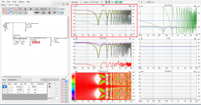
The interference stuff was done on VituixCAD, which is my favorite, can do all kinds of stuff. Attached is how to replicate the experiment. Use ideal drivers, use Z coordinate to create path length difference, tweak the SPL graph to show the magnitudes. Filter and gain nodes to test out stuff, listening distance is in the Options.
All in all, I've learned that visualizations make the message so much more powerful and I like making them here since I learn a lot from them and hopefully others pick a thing or two from them. I wish Youtube existed 20 years earlier... University math would have been so much easier just by watching youtube videos available today. Amazing visualizations and narrators in comparison to the boring projector lectures, was a struggle to stay awake.
If you want to see more specular reflections, their time / magnitude scale and what not, check out this one, this is not mine but some one else https://amcoustics.com/tools/amray
Unfortunately this doesn't show the angles but there is important stuff you can learn from it as well, like how many orders of first reflections your room fits before reverberation, what is their magnitude, what are their angles etc. Basically the first reflections have greatest magnitude, smallest angle, and thus are hardest to attenuate (by loudspeaker directivity) so basically best thing one can do is try and have them sound like the direct sound I think.
The interference stuff was done on VituixCAD, which is my favorite, can do all kinds of stuff. Attached is how to replicate the experiment. Use ideal drivers, use Z coordinate to create path length difference, tweak the SPL graph to show the magnitudes. Filter and gain nodes to test out stuff, listening distance is in the Options.
All in all, I've learned that visualizations make the message so much more powerful and I like making them here since I learn a lot from them and hopefully others pick a thing or two from them. I wish Youtube existed 20 years earlier... University math would have been so much easier just by watching youtube videos available today. Amazing visualizations and narrators in comparison to the boring projector lectures, was a struggle to stay awake.
Attachments
Last edited:
Hi, yeah the baffle step would be part of the equation. Basically, narrow baffle would let the sound to the wall behind the speaker. Resulting reflection would interfere with direct sound and create dips again depending on the distance. Front wall is kind of special since it is behind the sound source, sound going there and back towards the listener makes really long path length difference and the effect gets to bass frequencies real quick, basically the speaker needs to be 1/8wl from the front wall to couple to it above which the interference starts. On the contrary, floor bounce has usually the shortest path length difference of all reflections making it the highest in frequency. VituixCAD has simple room corner simulation available which shows that it is quite easy to have a speaker in position where there is dip(s) from the nearby boundaries, including floor and ceiling, front and side wall, combining more or less well.So if you measure a hollow at 200-300 Hz it is due to baffle step/xover more than reflections from the group, I bet on that.
The thing is the simulation is just that, and doesn't include the opposite side wall or back wall and what not. Although, it shows that one can utilize height of the speaker to balance out some of the worst looking dips due to the position on the floor. This is exactly how I got interest on the height and vertical reflections. Especially situation where the position of a speaker is quite set in stone (like family livingroom) the vertical dimension gives some adjustability. For this reason my big 3-way prototype is modular so that height of the ways can be adjusted.
Thanks for all these interesting information man...
I found this which looks interesting, just a thought
https://www.limmerhorns.de/630-bc1/
I found this which looks interesting, just a thought
https://www.limmerhorns.de/630-bc1/
Hello,
you guys could watch that french video, english subs seem available, it is very very interesting. Speaker and room influence, correction...
you guys could watch that french video, english subs seem available, it is very very interesting. Speaker and room influence, correction...
I have decided to build a cheap, basic modular box(s) so i can experiment with height of drivers. Just 16 mm chip board. A sealed box for woofer and for the mid driver too. If I plan on having the horn on the front baffle of my original plan, then I should probably mount the horn to a board as well in my test box. But who knows, If I like the sound of the woofer in a sealed box then I could make a modular system with the horn sitting free on top of the mid box.
any thought on this?
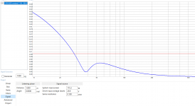
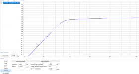
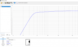
Its Just that the original ported design goes deeper without eq. (F3 about 40hz), but requires of course, a larger enclosure hence the tall rectangular coffin and that comes with a large front baffle.
I know its a question for another thread maybe but....... what sounds better at low frequencies say 40 hz, my driver in a QB3 alignment with no eq. or in a sealed box Qtc about .62 with 7db of EQ. at 40hz.? It appears in modelling with winisd that the group delay is less in the closed box ( even with eq) than the 115 l box tuned to 40hz. !
any thought on this?
Its Just that the original ported design goes deeper without eq. (F3 about 40hz), but requires of course, a larger enclosure hence the tall rectangular coffin and that comes with a large front baffle.
I know its a question for another thread maybe but....... what sounds better at low frequencies say 40 hz, my driver in a QB3 alignment with no eq. or in a sealed box Qtc about .62 with 7db of EQ. at 40hz.? It appears in modelling with winisd that the group delay is less in the closed box ( even with eq) than the 115 l box tuned to 40hz. !
Hi, freestanding horn/waveguide is fine. If you want better it make smooth mouth termination for it but there is only so much you can do without modifying the waveguide. Putting it on a baffle, without roundovers, would just introduce even more diffraction interference, lower in frequency the wider the baffle.
For the bass, I would use EQ regardles of the alignment. Prototype box is very good idea and I would go with sealed at first. When you measure in room response you might find out there is need to EQ bass down and if it happens around the Fs the porting would have been in vain 🙂 for home use that is, assuming excursion and heat is not problem and sufficient amplifier power is available.
For the bass, I would use EQ regardles of the alignment. Prototype box is very good idea and I would go with sealed at first. When you measure in room response you might find out there is need to EQ bass down and if it happens around the Fs the porting would have been in vain 🙂 for home use that is, assuming excursion and heat is not problem and sufficient amplifier power is available.
- Home
- Loudspeakers
- Multi-Way
- Faital & 18 Sound 3 way