That sounds interesting! Care to share (maybe start your own thread on the topic)? I would love to know what you've tried, and what you've learned. 🙂...I have been mostly interested in trying to use the KMG trickery on low voltage stages, with j113 jfets.
A while ago, I too played around with a J113 on an 18-volt supply (two 9V batteries in series), and I found that this particular JFET produced a surprising amount of voltage gain (due to very high transconductance), and also a very high amount of nonlinear distortion, compared to older JFET types such as, say, an MPF 102.
But I didn't try any of KMG's tricks, just a straight-forward common-source gain stage with a fully bypassed source resistor. I used it as an input stage to slightly "warm up" a guitar cab sim circuit I designed and built.
Until you load the output, it doesn't affect the sound. But when you connect a fairly heavy load that has an impedance that varies with frequency - like a Fender tone stack - then the frequency response gets affected by the high output impedance....the output impedance and how that affects the sound, interesting new angle.
At frequencies where the load impedance falls, the frequency response will dip. At frequencies where the load impedance increases, the frequency response will peak.
That made the tone-stack produce different EQ curves than the same tone-stack in a "toob" amp. The changes were significant, and audible.
-Gnobuddy
I am convinced this is doable. I take a "HiFI" powerstage with a specific pre-amp and am happy with it.I still have a dream that it is possible make a simple solid state guitar amp that behaves and sounds 'rock&roll'. But it has to be Lo-Fi, as you say, basically a bad amplifier. It should be like a vox or fender 5e3, biased well into class A region, no or very little feedback. And use jfets where you can.
At some stage I even use these terrible Si_Diode limiters - so my taste is in some aspects adverse to Gnobuddys.
For me it is useless to debate about "the ideal tube sound". I never liked sagging power supply and hated blocking distortion.
That's me. And you have to choose your individual holy grail of sound.
Before putting it out there, want to do some more real world building and testing first, so far it has mainly been on the drawing board and in the simulator. It is nice to know there are others who are enthousiastic about this stuff!That sounds interesting! Care to share (maybe start your own thread on the topic)? I would love to know what you've tried, and what you've learned. 🙂
A while ago, I too played around with a J113 on an 18-volt supply (two 9V batteries in series), and I found that this particular JFET produced a surprising amount of voltage gain (due to very high transconductance), and also a very high amount of nonlinear distortion, compared to older JFET types such as, say, an MPF 102.
But I didn't try any of KMG's tricks, just a straight-forward common-source gain stage with a fully bypassed source resistor. I used it as an input stage to slightly "warm up" a guitar cab sim circuit I designed and built.
Until you load the output, it doesn't affect the sound. But when you connect a fairly heavy load that has an impedance that varies with frequency - like a Fender tone stack - then the frequency response gets affected by the high output impedance.
At frequencies where the load impedance falls, the frequency response will dip. At frequencies where the load impedance increases, the frequency response will peak.
That made the tone-stack produce different EQ curves than the same tone-stack in a "toob" amp. The changes were significant, and audible.
-Gnobuddy
Marshall Lead 12 (model 5005) is fairly small and simple, fully solid state and definitely sounds "rock & roll". As far I remember ZZ Top uses one.I still have a dream that it is possible make a simple solid state guitar amp that behaves and sounds 'rock&roll'. But it has to be Lo-Fi, as you say, basically a bad amplifier. It should be like a vox or fender 5e3, biased well into class A region, no or very little feedback. And use jfets where you can.
Another interesting SS amp is Sunn Beta Lead with very nice overdriven tone.
I must say that Marshall sounds pretty good. But to me, there is still something lacking.. I looked up the schematic, and it is actually almost identical to the Rod Elliott amp, but less power.Marshall Lead 12 (model 5005) is fairly small and simple, fully solid state and definitely sounds "rock & roll". As far I remember ZZ Top uses one.
Another interesting SS amp is Sunn Beta Lead with very nice overdriven tone.
I'm working on my own layout of preamp part, this paired with some class D module should provide some cool heavy sound with lots of power.
And if you are happy with it, you are a lucky man. 🙂I am convinced this is doable. I take a "HiFI" powerstage with a specific pre-amp and am happy with it.
Several years ago, right here on diyAudio, I remember that you posted a sound clip from your setup, without saying what it was, and you asked on diyAudio that people listen, and then guess the type of amplifier that produced the sound. I remember replying that the distortion sounded harsh to me, that the onset of distortion sounded abrupt and not progressive, and that these characteristics made me think it was most likely a solid-state amp.
You never replied to my post, but later on you had other posts on diyAudio where you showed solid-state preamp designs based around the tanh() transfer function of a differential amplifier stage (aka "long tailed pair"), and you also mentioned that you did not use any tube amps any more. So I guess my ears heard correctly.
They have been very popular for many years, because they are so simple, and easily produce a harsh distortion that many teenage boys seem to like.At some stage I even use these terrible Si_Diode limiters...
For instance, Marshall sold a pedal called "Guv'nor" that consisted entirely of linear op-amp stages, with a series 1k resistor and an anti-parallel diodes to ground to create distortion. I don't know how many they sold, but they were available for a while, so evidently there is a market for such crude-sounding devices. ( Marshall Guv'nor: https://www.electrosmash.com/marshall-guvnor-analysis )
Harsh guitar distortion isn't limited to analogue circuits. In the digital domain, Zoom put a picture of a curve very much like the tanh() function on the outside of their Zoom G3 and G5 digital multieffects boxes, and the advertising included the claim that "A newly developed sigmoid curve clipper re-creates the smooth clipping of a tube amplifier's waveform"
The Zoom G3 was quite popular and sold well. I bought one, but I found the distortion harsh and unpleasant. Listening to it for a few minutes would give me ear-fatigue. The G3 has been gathering dust in the back of my closet for years now.
Before the G3, I had a Digitech multiFX pedal (RP-something) that also produced harsh, ear-fatiguing distortion. At various times, I had a Line 6 Pod 2.0, a Line 6 Spyder II, and a Line 6 Spyder Jam. All sounded harsh and "honky" and horrible to me. Yes, I was a fool three times over, and bought three different expensive products, based on many positive reviews from happy owners. Line 6 promised dozens of glorious tube amp simulations in one box, but what they actually delivered was the sound of half a dozen different kinds of kazoo in one box:
Not all tube amps have lovely rich guitar distortion. Many don't. It also doesn't mean mean it is impossible for any solid state amp to produce rich distortion. I've heard a few that sound very good, all of them involving some sort of deliberate or accidental duty cycle modulation.
One person - a Russian engineer who went by "KMG" on the Internet - came up with a scheme that was head and shoulders beyond any other analogue solid-state guitar amplifier sound I have ever heard.
It's all become rather moot of late; cheap DSP chips have finally become powerful enough to run really good valve emulation algorithms. The $76 (USD) Flamma Preamp sounds excellent to me, and contains 7 amp models, each with a drive and a clean channel.
This has a great deal to do with the type of music you play, and the FX pedals you may or may not use. For example, if you play short, sharp, percussive flamenco guitar, you certainly will not like power supply "sag" and the "slow" sound that comes with it.I never liked sagging power supply
One thing to think about: the initial transient at the beginning of each guitar note is often 10 - 20 dB bigger than the rest of the waveform. That's a huge spike.
In your LTP-based preamp, and in most op-amp guitar input stages, the circuit does not have the overload headroom to cope with a spike like that. The result is that this initial spike at the beginning of every guitar note produces a very short, harsh burst of distortion as the circuit is driven hard and abruptly far beyond its linear operating range.
I think this is one of the reasons why many solid-state guitar circuits sound harsh to me, even for clean tones.
It is not easy to simulate the huge initial transient in a guitar signal using LTSpice, but the effect can be seen even without the initial big transient, simply by making the input signal an exponentially damped sine wave (like an ideal guitar string picked and allowed to decay towards silence).
I did a simple simulation like this, of an LTP with a damped sinusoidal guitar note fed into it, and you can see the results in the attached image. Guitar signal has been adjusted to 3Vpp initially (a number which I, and others, have seen on an oscilloscope capture direct from an electric guitar). The output of the LTP clips very harshly at first, then as the signal decays there is a brief period of "soft" distortion, quickly giving way to the typical solid-state "too clean", zero-distortion signal.
A real guitar signal is much more complicated, containing multiple frequencies simultaneously; putting that through this sort of harsh initial clipping is going to generate a nasty mess of intermodulation distortion and high-order harmonics at the output. This is probably why the distortion sounds harsh.
When the input stage is a half-12AX7 vacuum tube, input nonlinearities smooth off that huge spike. A typical triode is biased at -1.5 volts Vgk, and small amounts of input grid current begins to flow at about Vgk = (-0.9V), gently rounding off guitar signal peaks. That means any signal peak from the guitar that's bigger than roughly 0.6 volts, starts to be gently and softly limited by the vacuum tube.
Not only is the input not harshly clipped; the high supply voltage (typically 250V - 350V for the preamp), combined with the limited voltage gain of each triode stage (typically 50 times, or 34 dB), also keep the output waveform from clipping hard.
That process continues in subsequent triode stages in the preamp, with the huge spike gradually softened by each successive stage.
In tube power amp stages, power supply sag may add to this effect.
The end effect is the smooth, rich clean tones of a really good tube amp. An old Fender Twin or AB763 based amplifier, for instance.
I found that using common-source JFET stage as the input, with a fully bypassed source resistor, does audibly reduce solid-state harshness for guitar clean tones. I think this is because of the nonlinear curvature of the JFETs Vgs/Id curve at low voltages, which rounds off the big starting transient from the guitar signal without harshly clipping it, somewhat like a triode (valve) does.
To my ears the JFET input definitely helps, but still does not sound as good as a really good tube amp.
Does anybody like it? It sounds like your guitar amp is "blowing a raspberry"....and hated blocking distortion.
I guess in the era of rock excess, some guitarists did enjoy making rude and unpleasant noises with their guitars.
In my little 2-watt 6AK6 guitar amp, I had to increase the output grid stoppers to, I think, 220k to virtually eliminate blocking distortion. Pentode input capacitance is very small, and 220k series resistance does not lower the amplifier bandwidth enough to matter with electric guitar signals (nothing good above 6 kHz from an e-guitar).
Dunno about holy grail, but I think the clean tones at about 7 minutes, 10 seconds into this clip are excellent:That's me. And you have to choose your individual holy grail of sound.
In fact I think that amp sounds excellent throughout the demo - and I think not many amps, tube or solid-state, sound as good.
All this reminds me of a visit I made to an art gallery in Pasadena, California, many years ago. There was an exhibition of Western art spanning several centuries of work. The oldest paintings were relatively crude, but as the centuries progressed and the art of painting continued to be developed, the later paintings became more and more amazing to look at. The sheer fabrics looked translucent, the satins shone with a soft lustre, the eyeballs looked wet, you could see the softness of the curtains and furnishings, the hardness of the glasses and goblets, and almost see the blood rushing by just under the beautiful skin of the subjects.
The improvements in the quality of the art were amazing - but this amazing improvement was made up of hundreds of tiny, tiny improvements, each one almost imperceptible by itself.
You can look at a picture of Spider Man in a comic book, and recognize that it is a representation of a male human being.
Or you can look at the attached poor copy of one of Élisabeth Vigée Le Brun's paintings, and see that it is a representation of a female human being. But what a difference from the simple crude drawing of Spider Man!
Guitar amplifiers span a similar range. Diode clippers get you Spider Man. The Wang amplifier in the Darrel Braun demo gets you Vigée Le Brun.
There is certainly a place for Spider Man in the world, as the immense popularity of the comic books attests to.
But Spider Man does not give one the immersive, deeply involving aesthetic experience that Vigée Le Brun's work can.
-Gnobuddy
Attachments


Nothing wrong with your technical analysis. Obviously we do not share the same perception when it comes to "harshness" of sound. As you know my old contributions on SS-guitar amps, and there have been no substantial changes during the last years another extra thread looks not very entertaining to me.
Looking at the trace it seems the top side is rounded off and the bottom more sharp. Maybe run the signal through a splitter first and then two stages as shown then collect the two top waves? Might be less harsh to you.One thing to think about: the initial transient at the beginning of each guitar note is often 10 - 20 dB bigger than the rest of the waveform. That's a huge spike.
In your LTP-based preamp, and in most op-amp guitar input stages, the circuit does not have the overload headroom to cope with a spike like that. The result is that this initial spike at the beginning of every guitar note produces a very short, harsh burst of distortion as the circuit is driven hard and abruptly far beyond its linear operating range.
I think this is one of the reasons why many solid-state guitar circuits sound harsh to me, even for clean tones.
It is not easy to simulate the huge initial transient in a guitar signal using LTSpice, but the effect can be seen even without the initial big transient, simply by making the input signal an exponentially damped sine wave (like an ideal guitar string picked and allowed to decay towards silence).
I did a simple simulation like this, of an LTP with a damped sinusoidal guitar note fed into it, and you can see the results in the attached image. Guitar signal has been adjusted to 3Vpp initially (a number which I, and others, have seen on an oscilloscope capture direct from an electric guitar). The output of the LTP clips very harshly at first, then as the signal decays there is a brief period of "soft" distortion, quickly giving way to the typical solid-state "too clean", zero-distortion signal.
In the simulation, there is even some sort of frequency-doubling happening during severe overload (look the tops of the first few waveforms, with two separate peaks crammed in where there should be only one).Looking at the trace it seems the top side is rounded off and the bottom more sharp.
I think this just shows that if an electronic circuit - particularly one with high voltage gain, running on low DC supply voltage - is overdriven sufficiently hard, all sorts of bad behaviour is likely to emerge. (The simulation is running on +/- 15V rails, quite generous compared to the usual 9V effects pedals.)
At the other extreme, my little Fender Mustang Micro runs on a single lithium cell (4.2 V DC fully charged). But it exhibits no audible trace of clipping on clean-tone settings, including the HiFi-clean studio preamp model.
Newer microcontrollers and DSP chips seem mostly to run on 3.3 volts DC, so I speculate that the A/D converter inside the Mustang Micro is likely to be a 3.3V device. If so, it will clip harshly and very unpleasantly if the input signal ever goes below 0 V or above 3.3 V.
How did Fender engineers keep harsh clipping from happening? I suspect the incoming guitar signal is immediately fed through a voltage divider, and cut down to a much smaller amplitude before it hits the first electronic device.
This is traditionally thought off as a bad thing to do, as it makes signal/noise ratio worse - but maybe it is the right solution for solid-state amps running on low voltage?
-Gnobuddy
Sorry but wrong analysis: you are thinking analog.Newer microcontrollers and DSP chips seem mostly to run on 3.3 volts DC, so I speculate that the A/D converter inside the Mustang Micro is likely to be a 3.3V device. If so, it will clip harshly and very unpleasantly if the input signal ever goes below 0 V or above 3.3 V.
The DSP inside never ever sees a sinewave , but its digitized representation.
Swinging from +3.3V to zero, no matter the audio signal amplitude, swinging even with zero signal, and at clock frequency, completely unrelated to original signal frequency.
Absolutely different Worlds.
Me think you should re-think your replySorry but wrong analysis: you are thinking analog.
The DSP inside never ever sees a sinewave , but its digitized representation.
Swinging from +3.3V to zero, no matter the audio signal amplitude, swinging even with zero signal, and at clock frequency, completely unrelated to original signal frequency.
Absolutely different Worlds.
Me thinks you should look closer at how a DSP or any digital device works 🙂
Hint,and just as a starter:
Hint,and just as a starter:
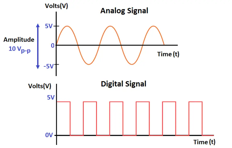
Analog Signals
Analog Signals
Analog signal is a form of electrical energy (voltage, current or electromagnetic power) for which there is a linear relationship between electrical quantity and the value that the signal represents.
The signal whose amplitude takes any value in a continuous range is called analog signal.
Analog Signals are continuous in nature which vary with respect to time. They can be periodic or non-periodic.
Voltage, current, frequency, pressure, sound, light, temperature are the physical variables that are measured with respect to their changes with respect to time to obtain information.
When voltage versus time graph is plotted we see curve with continuous values like sine waves.
Analog to digital converter converts analog signal to digital signal by a process called sampling and quantization. Sound waves are converted to sequence of samples by the process Sampling
Or, in your more modern microprocessor/DSP 0V and 3.3V .... but nothing in between, and there is NO voltage peak variation related to signal level.Digital Signals
The signal, whose amplitude takes only limited values is called Digital signal.
Digital signal are discrete, they contain only distinct values.
Digital signals carry binary data i.e. 0 or 1 in form of bits, it can only contain one value at a period of time. Digital signals are represented as square waves or clock signals.
The minimum value is 0 volts whereas maximum value is 5 volts.
Last edited:
Hey, you do not need to point me to the basics. The point Gnobuddy made was that a DSP powered with 3.3V with on-board ADC will accept max 3.3Vpp analog input level.
Hey, you do not need to point me to the basics. The point Gnobuddy made was that a DSP powered with 3.3V with on-board ADC will accept max 3.3Vpp analog input level.Me thinks you should look closer at how a DSP or any digital device works 🙂
Hint,and just as a starter:
Or, in your more modern microprocessor/DSP 0V and 3.3V .... but nothing in between, and there is NO voltage peak variation related to signal level.
He didn´t say so.
Please read his own words, 10 times if necessary.
Please read his own words, 10 times if necessary.
"IT" refers to the A/D converter and "the" input signal can be anything ; just think how a Multimeter can measure up to 1000V, or any voltage above 3.3V .Gnobuddy said:
Newer microcontrollers and DSP chips seem mostly to run on 3.3 volts DC, so I speculate that the A/D converter inside the Mustang Micro is likely to be a 3.3V device. If so, it will clip harshly and very unpleasantly if the input signal ever goes below 0 V or above 3.3 V.
So what?Newer microcontrollers and DSP chips seem mostly to run on 3.3 volts DC, so I speculate that the A/D converter inside the Mustang Micro is likely to be a 3.3V device. If so, it will clip harshly and very unpleasantly if the input signal ever goes below 0 V or above 3.3 V.
-Gnobuddy
Oh, I most certainly did. But evidently I didn't make it clear enough. Since everyone on this thread understands how an A/D converter works, I did not think I would need to dot every "i" and cross every "t". Sorry about that.He didn´t say so.
Bucks Bunny understood me correctly.
Let me spell it out in more detail, since it wasn't sufficiently clear from my earlier post.
The DC reference voltage fed to onboard A/D converters is never more than the B+ voltage fed to the entire microcontroller; often it is less.
An A/D converter cannot correctly convert any analogue input voltage greater than its internal DC reference voltage to a digital representation. It also cannot correctly convert any analogue input voltage below zero volts to a correct digital representation. It only "understands" analogue voltages between zero volts, and the internal DC reference voltage used in that particular A/D converter.
Therefore, 3.3V DSP chips have onboard A/D converters that cannot read any ANALOGUE input voltage that goes above +3.3V, or below 0V. If the analogue signal goes above, +3.3V, the digital representation will "flat top" at the maximum count of the A/D converter; for example, 65,535 if it is a 16-bit converter. The A/D converter will continue to output a stream of numbers, all with the value 65,535, for as long as the input analogue voltage is greater than 3.3 volts.
And if the analogue signal drops below 0V, the A/D converter will "flat bottom" and spit out a stream of digital "0" codes for the entire duration the analogue signal stays below 0 volts.
The result is that the digital output will be clipped, even more harshly than analog clipping that "flat-tops" at 3.3V and 0 V.
Garbage in, garbage out; converting to the digital domain does not help at all if you screw up the conversion itself.
Elsewhere on diyAudio, at least one person has proved (with 'scope captures) that he can get a 10-volt peak-to-peak signal out of his humbucker-equipped electric guitar.
10 Vpp is unusual, but it doesn't seem to be hard to generate 3 volts peak-to-peak from typical humbucker-pickup guitar.
I hear no audible clipping from the output of my Mustang Micro.
Ergo, Fender engineers were smart, and found some way to avoid clipping the analogue input stage and A/D converter in the Mustang Micro.
Before someone starts to complain that analogue signals do fall below zero volts, yes, that is true. That problem is fixed by applying a DC bias equal to half the A/D converter's internal reference voltage, to the analogue signal, before it is fed into the A/D converter.
In the case of a 3.3V internal A/D reference voltage, it would be typical to bias the input analogue signal by +1.66 volts. The signal can then fluctuate about this value by up to a maximum of +/- 1.66 volts. If it goes beyond either of those bounds, the A/D converter will clip, and the DIGITAL signal coming out of it will represent a harshly clipped signal.
-Gnobuddy
Last edited:
I hope this is all cleared up now. The picture you posted is too simplified, and assumes the A/D converter itself is not clipped.Sorry but wrong analysis: you are thinking analog.
The DSP inside never ever sees a sinewave , but its digitized representation.
This works perfectly in an ideal world, where the A/D converter has far more input range than the incoming analogue signal.
But reality is different. Reality is that the analogue signal enters the A/D converter, and the A/D converter will not produce a correct "digitized representation" if the analogue input signal is not within the proper input range for the A/D converter input.
With 3.3V devices, that means the input analogue signal has to stay between zero volts and +3.3V at all times, otherwise it will get digitally clipped by the A/D conversion process.
So I am not thinking wrong; if you feed an out-of-bounds analogue signal into an A/D converter, you get digital clipping. If anything, it sounds even worse than analogue clipping.
This is one reason why the old standard for CD audio mixing was to keep the audio signal level at about (-12 dB) below clipping (usually marked as 0 dB). It was vitally important never to clip, even for a split second, because digital clipping sounds absolutely horrible.
-Gnobuddy
Did I miss the part where a signal of any size can be reduced with a voltage divider to fit into the A/D?
- Home
- Live Sound
- Instruments and Amps
- Building a SS guitar amp