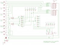
rev 0.3
One correction. Zeners were not tied to the GND in previous schematics.
More info added.
Since I delete the previous rev. images from my Flickr to minimize misleading web surfers, there's no point to link them here, so only the PDF version is attached.
One correction. Zeners were not tied to the GND in previous schematics.
More info added.
Since I delete the previous rev. images from my Flickr to minimize misleading web surfers, there's no point to link them here, so only the PDF version is attached.
Attachments
Hi,
I am restoring an amplifier A1, replacement capacitors, some resistors, and voltage offset adjustment. The unit is like new, and I'll use it as a monitor for my CD player upgrades.
I need the scheme to facilitate my work .
.
Greetings from Spain
I am restoring an amplifier A1, replacement capacitors, some resistors, and voltage offset adjustment. The unit is like new, and I'll use it as a monitor for my CD player upgrades.
I need the scheme to facilitate my work
. Greetings from Spain
I'm faced with an interesting issue..
NO ONE HAS PRE-AMP SCHEMATIC FOR V1
I really just need proper values for preamp Resistor and Zenner R504+R503 and D507+D508
I've even contacted Cambridge tech support, they have no info on V1 but do on V2&3
PLEASE HELP!
NO ONE HAS PRE-AMP SCHEMATIC FOR V1
I really just need proper values for preamp Resistor and Zenner R504+R503 and D507+D508
I've even contacted Cambridge tech support, they have no info on V1 but do on V2&3
PLEASE HELP!
It seems there is a reason why Cambridge audio can't supply the schematic to the first, discrete amp. version - it's not entirely their design. Perhaps you could still email Mike Creek or member X-pro and ask for help with the preamp section.
http://www.diyaudio.com/forums/soli...dge-audio-a1-power-amp-section-schematic.html
http://www.diyaudio.com/forums/soli...dge-audio-a1-power-amp-section-schematic.html
Hi All,
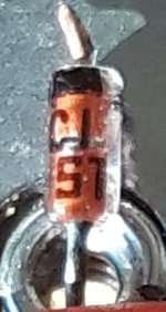
I am trying to identify zener diodes ZD1 and ZD2 (A1 mk3, LM4766 version).
Mine have been corroded by the glue around the capacitors.
I need to know the voltage and wattage so I can order replacements. I have attached a picture of one of them - it seems to have "C151" (or maybe "C157") marked on it, but I can't find what that code means.
Judging by the size (4.2mm x 1.8mm) it looks like its 500mW but I'm not sure.
The brilliant schematic posted by Mortymore rates these as 10v, but on the circuit board next to U2 (4558 opamp) it says "15v", which makes me wonder if the zeners are 15v?
Can anyone help?
Attachments
Thanks Jaycee
I just measured the zener voltage of one of the diodes I pulled from the A1, and it is indeed 15v. Thanks for confirming.
I just measured the zener voltage of one of the diodes I pulled from the A1, and it is indeed 15v. Thanks for confirming.
Did you measure the voltage drop across this zener to find it has failed or is this a concern for the prospect of that happening in the future. To me this looks more cosmetic and not an indication of imminent failure.
mjona, the zeners themselves were ok, but the glue they used around the capacitors becomes corrosive over time and it had corroded the legs of the zeners. I removed them to clean the board up and the leg of one of them broke.
Hot melt gunk, the thinking might have been to seal these from airborne moisture and contaminants. I live in a valley area where mist is common in winter after it rains. You can use silica get packs to absorb residual kitchen, laundry and bathroom moisture that gets around the home. I put some inside my equipment.
A1 mk3 phono module
OK, having got my A1 cleaned up and working, I am thinking of affordable ways to add a phono stage module. Either making one, or salvaging from a broken amp from eBay.
I'm confused though - The pins on the input board that feed the phono preamp module include a +ve and -ve power connection which is taken via connector "CON2A" from the main board to the input board.
However on my A1 mk3, CON2A has only 5 pins - 4 pins for the audio signal (two shielded cables) and 1 pin for +ve (orange wire).
This means there is no -ve power on the input board and the -ve pin seems to be shorted to ground.
The A1 mk3 SE, A1 mk1, and the equivalent Ariston AX-900/910 all seem to have 6 wires from the main board to the input board and include a blue wire that is presumably -ve.
Does this mean that a phono module board taken from a mk3 SE, mk1 or Ariston amp, will not work with my A1 mk3?
Last edited:
An update for anyone who is interested: I bought an Ariston AX-900 which had the Cambridge Audio phono module fitted, and transferred it to my A1 mk3.
It works fine. It looks like the -V rail present on the input boards of some amps is not used in the phono amp and it only requires +V. 🙂
It works fine. It looks like the -V rail present on the input boards of some amps is not used in the phono amp and it only requires +V. 🙂
Hi all,
I have just had the transformer in my A1 V3.0 die. I can't find anything related to the part code written on the thing, besides another post where somebody, like me, is trying to replace it. It says on the case that the max power consumption is 150W, I just wanted to check If I was to replace it with any 240: 24+ 24- 150W transformer, I am likely to run into any issues. Also, 150W seems like a lot, but that is what's written on the back of the maching as being 'max power consumption'.)
The existing transformer is showing continuity (/low resistance) across all of its output wires, and nothing (resistance beyond the scale of my meter) across the input, none of the fuses have blown either. Is the problem likely to be isolated to the transformer? It seems really strange that the fuses are all still intact, so it wasn't damaged by a power surge or something like that. I have no intuition regarding what caused this. Is there anything I should be aware of that may cause a replacement to blow too?
I appreciate your time reading this
If the primary side is genuinely open circuit then it sounds like the transformer has a thermal fuse embedded in the windings. These are normally non replaceable.
The transformer for the A1 diagram I have is shown as 120va rated so you need to physically measure the diameter and height to make sure a replacement will fit. You can go higher on the va rating such as 160 va.
The DC rails are shown as -/+28 volt DC and that translates to a 20-0-20 volt AC transformer. A 24-0 -24 volt AC transformer would give around -/+ 34 volts DC which is to high.
Given that transformers are rated at maximum load current an 18-0-18 volt type could be a safer bet. The voltage will be higher at low to moderate loading by a percentage equal to the regulation figure given in the transformer data sheet. This could be 3 or 4% for such a transformer.
Why has it failed?
It may just have failed for no reason. It happens. Thermal fuses are as much a nuisance as they are a help in many cases. Given that none of the other fuses have blown make this a real possibility.
Also possible would be a short on the secondary side such as a failed rectifier in the bridge or a failed output chip as these would cause a thermal fuse to fail.
Most transformers you will be looking at will not have thermal fuses fitted.
Always power the amp up using a DBT (dim bulb tester) initially to make sure no obvious shorts exist.
ok, I really need to do some reading up on transformers and the disparity, as you describe, between the AC and DC voltages. This and the schematics posted by Mortymore and I just found this picture of someone measuring the output as 25V, it is very confusing to me.The DC rails are shown as -/+28 volt DC and that translates to a 20-0-20 volt AC transformer. A 24-0 -24 volt AC transformer would give around -/+ 34 volts DC which is to high.
good information about the thermal fuse and dim bulb tester is a great suggestion, thanks for that.
That looks a physically small transformer which implies the regulation will be poor... that's just the way it is with all small transformers. The AC voltage is high at light loading and falls as you draw significant current. Toroids are generally better for regulation.
The DC voltage you get after rectification equals the AC voltage multiplied by root 2 (1.414) so a 25 volt AC input as in that picture would give 25*1.414 which is 35 volts DC. So that would give -/+35 volts DC or 70 volts in total.
(We should also account for the bridge rectifier volt drop which will knock a volt or so off those numbers but in practice with voltage this high it makes little practical difference)
Lets look at the TDA1514A chip. Here is the data sheet:
TDA1514A
The maximum supply is quoted as -/+30 volts and so already we have an apparent issue if you are applying -/+35 volts. This kind of anomaly is sadly quite common and the bottom line is the chip is being run to within an inch of its life. Under heavy loading (playing loud) the voltage will fall a little.
This is where I got the 28 volts from:

and working back from that gives 28/1.414 giving 20 volts AC.
I was also thinking it would be a toroidal transformer rather than an EI type construction. If a toroidal would fit and you struggle to get a replacement of the correct type and size then it might be an option.
You would have to weigh up if something like this would fit. Off load the voltage is quoted as 19.6 volts. Also remember these are quoted at 230 volts AC mains and so if your mains is higher (here it is nearer 243v) then the secondary voltages are higher again by that percentage difference.
https://cpc.farnell.com/multicomp/mcta120-18/transformer-120va-2-x-18v/dp/TF01396
I would recommend you check the diodes in the bridge first and also check for short circuits across each supply rail (the - and + 28v rails). If there is a short then probably one of the chips have failed. Make sure you can obtain new chips before spending money on other parts. If there are no shorts it still does not mean one of the chips have failed.
The DC voltage you get after rectification equals the AC voltage multiplied by root 2 (1.414) so a 25 volt AC input as in that picture would give 25*1.414 which is 35 volts DC. So that would give -/+35 volts DC or 70 volts in total.
(We should also account for the bridge rectifier volt drop which will knock a volt or so off those numbers but in practice with voltage this high it makes little practical difference)
Lets look at the TDA1514A chip. Here is the data sheet:
TDA1514A
The maximum supply is quoted as -/+30 volts and so already we have an apparent issue if you are applying -/+35 volts. This kind of anomaly is sadly quite common and the bottom line is the chip is being run to within an inch of its life. Under heavy loading (playing loud) the voltage will fall a little.
This is where I got the 28 volts from:
and working back from that gives 28/1.414 giving 20 volts AC.
I was also thinking it would be a toroidal transformer rather than an EI type construction. If a toroidal would fit and you struggle to get a replacement of the correct type and size then it might be an option.
You would have to weigh up if something like this would fit. Off load the voltage is quoted as 19.6 volts. Also remember these are quoted at 230 volts AC mains and so if your mains is higher (here it is nearer 243v) then the secondary voltages are higher again by that percentage difference.
https://cpc.farnell.com/multicomp/mcta120-18/transformer-120va-2-x-18v/dp/TF01396
I would recommend you check the diodes in the bridge first and also check for short circuits across each supply rail (the - and + 28v rails). If there is a short then probably one of the chips have failed. Make sure you can obtain new chips before spending money on other parts. If there are no shorts it still does not mean one of the chips have failed.
The transformer specification is detailed below, the transformer often fails due to the failure of the Audio output integrated circuit mounted on the heat sink part number LM4766T, and can be ordered from RS Components https://uk.rs-online.com/web/p/audio-amplifier-ics/5343318/
When the LM4766T fails it can draw excess current and the thermal fuse inside the transformer goes open circuit.
If you remove the metal clamp across the lm4766t you my see physical damage and a burn mark around the pins of the IC.
Primary 0 - 230VAC
Secondary Dual 27-0, 27-0 VAC
VA 120
When the LM4766T fails it can draw excess current and the thermal fuse inside the transformer goes open circuit.
If you remove the metal clamp across the lm4766t you my see physical damage and a burn mark around the pins of the IC.
Primary 0 - 230VAC
Secondary Dual 27-0, 27-0 VAC
VA 120
Mooly Thanks for this. Good infomation but the schematic is not an A1 V3.0, or maybe more accurate/politer to say, its not the machine I have in front of me.The DC voltage you get after rectification equals the AC voltage multiplied by root 2 (1.414) so a 25 volt AC input as in that picture would give 25*1.414 which is 35 volts DC. So that would give -/+35 volts DC or 70 volts in total.
I dont see any signs of physical damage around the lm4766t, some questionable soldering on the back maybe, but nothing that would cause a problem.The transformer specification is detailed below, the transformer often fails due to the failure of the Audio output integrated circuit mounted on the heat sink part number LM4766T, and can be ordered from RS Components https://uk.rs-online.com/web/p/audio-amplifier-ics/5343318/
When the LM4766T fails it can draw excess current and the thermal fuse inside the transformer goes open circuit.
If you remove the metal clamp across the lm4766t you my see physical damage and a burn mark around the pins of the IC.
Primary 0 - 230VAC
Secondary Dual 27-0, 27-0 VAC
VA 120
Thanks for the transformer info. If i can find one cheap enough to make the fixing this thing make sense, i will swap out the lm4766t anyway just to be on the safe side.
Or.. im thinking outloud, because ive never done this before, could i tie in to Vcc and Vee with my benchtop powersupply? how closly matched would the +- voltages have to be? am i missing something obvious here? I could tie in easily using the legs of the diodes point 2 and 3 on the FBR? I wouldnt expect it to work nicly and i'd keep the voltage low, but atleast i'd see if there was a big overcurrent issue before spending any money?
- Home
- Amplifiers
- Solid State
- Cambridge Audio A1 Schematic