Hello gentlemen Can the Nelson Pass B1 rev 2 preamp be used with this amplifier in common source mode?
Bonjour messieurs Le préampli Nelson Pass B1 rev 2 peut-il être utilisé avec cet ampli en mode source commune ?
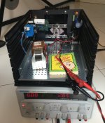
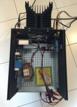
These are pictures from my last experiment with the THF-51S. It's a small FOKIN. The power supply is 24 Volt and the current about 2.6 Ampere. Only 60 Watt of Power Dissipation. The output power with 8 R is low. The measurements stop at just over 7 W. My measurements system does not allow me to go further. I think the maximum power does not exceed 12 W. The distortion is a little higher than Ben's FOKIN. However, weight and heat are more easily managed. Maybe it's not a bad idea to build the second channel and power each channel with a MEAN WELL (GTS160A24-R7B).
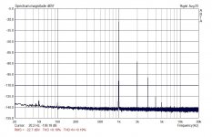
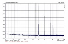
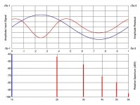
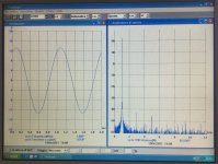
The Arta graphs are the measurements with 2.64 V, 5.84 V and 7.32 V on the load (8 R). The Diana residual (red) is with 7.75 V, the harmonics are normalized.
I used Peter Millet's interface for the DAC output and the ADC input of the sound card (EMU 1212). The chassis is the Galaxy 4U 230 x 280 mm + Base Plate 210 x 260 mm. The heatsink is 15 cm high and fits perfectly (after drilling) to the rear panel.
Attachments

I built only one channel. For what it's worth, I can say that Lianne La Havas is convincingly reproduced. I made a comparison with a Sony VFET Amplifier Part 2. I tried with only one working channel and I adjusted the volume of the pre (Luminaria) to have the same gain.
The distortion results look very good. I think you may be able to get more than 12W out of it with Iq at 2.6A, perhaps close to 18W at clipping. Choke loading is more efficient than CCS loading.
My choke loaded 2SK28 follower running at Vds of 21.0V and Iq of 1.5A clipped at around 12.5W at 8 Ohm.
My choke loaded 2SK28 follower running at Vds of 21.0V and Iq of 1.5A clipped at around 12.5W at 8 Ohm.
Thanks for the information. I will also build the second channel. But first I have to decide how to power it. Trafo + C-L-C or Mean Well.
I just made a CLC, with Ideal Bridge, even with low value capacitors it works well: 2.200uF - 22mH/0.25 ohm - 10.000uF, I get 44.5 volt in (the usual sawtooth) and 15mV RMS out at 2,7 amps; the residual is pure sine wave. 100Hz of course. The residual flutter from mains is low too (the common hiccups in the DC, just bursts of 10 mV in which the DC level changes). With an extra filter bank of 56.00uF Malory cans, all residue will vanish.
While unloaded it is 49Volt at 31.5V AC. So that is great performance.
Still I consider a SMPS , there are versions that have '‧Built-in active PFC function, PF>0.95', that is, it does not take power from the mains only at the top of the cycle, but during the whole mains cycle. Result: lower drain on the mains [and probably better recording of actual power use by the KWH meter. . .]
bonsoir messieurs
Je suis en train de monter mon THF-51 sur les dissipateurs thermiques, où puis-je acheter la meilleure isolation en feuille possible ?
Merci d'avance pour vos réponses.
Je suis en train de monter mon THF-51 sur les dissipateurs thermiques, où puis-je acheter la meilleure isolation en feuille possible ?
Merci d'avance pour vos réponses.
L'arternative c'est monter les SITs directement sur les radiateurs et isoler les radiateurs, comme par example avent une montage flottant sur bois (comme Ben Mah a fait)
triode_al and toto34, English please.L'arternative c'est monter les SITs directement sur les radiateurs et isoler les radiateurs, comme par example avent une montage flottant sur bois (comme Ben Mah a fait)
Translation using Google Translate:
"The alternative is to mount the SITs directly on the radiators and insulate the radiators, like for example before a floating assembly on wood (like Ben Mah did)"
That wasn't me. No wood in my amplifiers.

I have ran other test with the THF-51S. A voltage of about 23.5 Volt (Mean Well-24V + R-C filter) lowers the Vds too much. THD and output power deteriorated. It is a pity to use in this way a SIT with 400 Watt of the Total Power Dissipation. On the other hand, i have verified that the heatsink can safely dissipate about 67-70 Watt. A better operating point is this:
V+=28V Vds=25.7V Ids=2.67A
The triode-tipe distortion is good and the output power easily exceed 11W.
This is an FFT with my vintage gear (PICO + TEK SG505). The generator is at maximum. This way the project can continue.
V+=28V Vds=25.7V Ids=2.67A
The triode-tipe distortion is good and the output power easily exceed 11W.
This is an FFT with my vintage gear (PICO + TEK SG505). The generator is at maximum. This way the project can continue.
Attachments
Hi!
I posted on this thread some months ago as I was planning to build my first VFET amplifier. I gathered materials, but had to shelve the project to build some tube amplifiers and a DAC. Now I am back at it! Doing some planning and catching up on what has been tried here. Right now I am looking at doing a tube front end, followed by a JFET buffer, then THF-51S final.
Here is what I have in mind at the moment - type 37 CCS loaded tube gain stage wired as a hybrid mu-follower into a complementary JFET buffer DC-coupled to common drain THF-51S with choke load. This makes around 19W with a 1.5Vrms input sensitivity. Alternatively, the JFET buffer could use a pair of 2SK170 as a WCF.

Bandwidth is good in simulation.

I have some THF-51S, six in total, and nice thermal / insulating pads I bought way back when. Also a few examples of type 37 triodes. The amplifier could use type 76 as well.


Working on the power supply now, will post some more as things come along. Nothing finalized yet, just making plans.
I posted on this thread some months ago as I was planning to build my first VFET amplifier. I gathered materials, but had to shelve the project to build some tube amplifiers and a DAC. Now I am back at it! Doing some planning and catching up on what has been tried here. Right now I am looking at doing a tube front end, followed by a JFET buffer, then THF-51S final.
Here is what I have in mind at the moment - type 37 CCS loaded tube gain stage wired as a hybrid mu-follower into a complementary JFET buffer DC-coupled to common drain THF-51S with choke load. This makes around 19W with a 1.5Vrms input sensitivity. Alternatively, the JFET buffer could use a pair of 2SK170 as a WCF.
Bandwidth is good in simulation.
I have some THF-51S, six in total, and nice thermal / insulating pads I bought way back when. Also a few examples of type 37 triodes. The amplifier could use type 76 as well.
Working on the power supply now, will post some more as things come along. Nothing finalized yet, just making plans.
That looks like fun. Maybe need a coupling capacitor to go from +/– 24V JFet buffer to +32 / 0 V output stage?

- Home
- Amplifiers
- Pass Labs
- 25W Single Ended Hammond 193V Choke Loaded 2SK180 L'Amp