Hello to all. I am new to this forum and this is my first post.
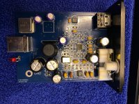
I have started DIY project of extension my old USB sound card DAC with optical audio input (TOSLINK). The usb DAC is based on SA9023 which is connected to ES0918K2M over I2S interface. Idea is to extend the board with Toslink reciever and connect it to ES9018K2M SPDIF input.


First step was to add Toslink receiver and connect its output to ES9018K2M GPIO2 as SPDIF input, after that plan was to use ES9018K2M GPIO1 as I2S\SPDIF input selector switch. To make that work ES9018K2M registers needs to be configured properly over I2C interface. I used raspberry Pi 3 Model B+ to establish I2C communication with ES9018K2M but was not able to detect the chip address 0x48:
pi@raspberrypi:~ $ i2cdetect -y 1
0 1 2 3 4 5 6 7 8 9 a b c d e f
00: -- -- -- -- -- -- -- --
10: -- -- -- -- -- -- -- -- -- -- -- -- -- -- -- --
20: -- -- -- -- -- -- -- -- -- -- -- -- -- -- -- --
30: -- -- -- -- -- -- -- -- -- -- -- -- -- -- -- --
40: -- -- -- -- -- -- -- -- -- -- -- -- -- -- -- --
50: -- -- -- -- -- -- -- -- -- -- -- -- -- -- -- --
60: -- -- -- -- -- -- -- -- -- -- -- -- -- -- -- --
70: -- -- -- -- -- -- -- --

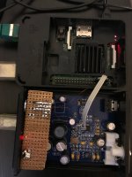
As it can be seen form picture above, SDA and SCL lines are pulled up by 4k7 resistors, cable to RPi3 is short and connected to corresponding GPIOs. I2C is enabled in rpi3 config and baud rate set to 100kHz. USB DAC board is powered from rpi3 via USB cable and works properly. Later, I removed 33 ohm resistors from I2S lines to disconnect SA9023 from ES9018K2M and exclude possible interference, but that didn't fix I2C communication problem.
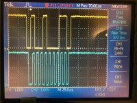
My next step was to connect oscilloscope and check I2C signals when sending command:
pi@raspberrypi:~ $ i2cget -y 1 0x48
Error: Read failed

Form picture above it is evident that for some, to me unknown reason, ES9018K2M doesn't put ACK signal to low.
Any help, or suggestion how to fix the issue is appreciated.
I have started DIY project of extension my old USB sound card DAC with optical audio input (TOSLINK). The usb DAC is based on SA9023 which is connected to ES0918K2M over I2S interface. Idea is to extend the board with Toslink reciever and connect it to ES9018K2M SPDIF input.


First step was to add Toslink receiver and connect its output to ES9018K2M GPIO2 as SPDIF input, after that plan was to use ES9018K2M GPIO1 as I2S\SPDIF input selector switch. To make that work ES9018K2M registers needs to be configured properly over I2C interface. I used raspberry Pi 3 Model B+ to establish I2C communication with ES9018K2M but was not able to detect the chip address 0x48:
pi@raspberrypi:~ $ i2cdetect -y 1
0 1 2 3 4 5 6 7 8 9 a b c d e f
00: -- -- -- -- -- -- -- --
10: -- -- -- -- -- -- -- -- -- -- -- -- -- -- -- --
20: -- -- -- -- -- -- -- -- -- -- -- -- -- -- -- --
30: -- -- -- -- -- -- -- -- -- -- -- -- -- -- -- --
40: -- -- -- -- -- -- -- -- -- -- -- -- -- -- -- --
50: -- -- -- -- -- -- -- -- -- -- -- -- -- -- -- --
60: -- -- -- -- -- -- -- -- -- -- -- -- -- -- -- --
70: -- -- -- -- -- -- -- --

As it can be seen form picture above, SDA and SCL lines are pulled up by 4k7 resistors, cable to RPi3 is short and connected to corresponding GPIOs. I2C is enabled in rpi3 config and baud rate set to 100kHz. USB DAC board is powered from rpi3 via USB cable and works properly. Later, I removed 33 ohm resistors from I2S lines to disconnect SA9023 from ES9018K2M and exclude possible interference, but that didn't fix I2C communication problem.
My next step was to connect oscilloscope and check I2C signals when sending command:
pi@raspberrypi:~ $ i2cget -y 1 0x48
Error: Read failed

Form picture above it is evident that for some, to me unknown reason, ES9018K2M doesn't put ACK signal to low.
Any help, or suggestion how to fix the issue is appreciated.
Usually a problem like that is that either the dac chip is set for SPI instead of I2C or else you are using the wrong I2C address (not sure if 9018 in particular supports SPI). I would probably use an Arduino with an I2C scanner program to check the I2C bus for any devices that respond. Other than that sometimes people get confused between 7-bit and 8-bit I2C address numbering so they try the wrong address for that reason. One might also check the dac pins to verify it is configured for I2C and to use the correct address.
My RPi detects ES9038Q2M with i2cdetect OK, provided the DAC chip is enabled via the enable pin (connected to one of RPi GPIOs in my case).
From the chip datasheet the only supported programming interface is i2c and chip address can be set to 0x90 or 0x92 (8-bit addressing). In my rpi3 i have used 0x48 ( and 0x49) 7-bit adress which corresponds to oscilloascope signal from picture above. I don’t have arduino but have seen lot of people successfully use rpi with es9018k2m.Usually a problem like that is that either the dac chip is set for SPI instead of I2C or else you are using the wrong I2C address (not sure if 9018 in particular supports SPI). I would probably use an Arduino with an I2C scanner program to check the I2C bus for any devices that respond. Other than that sometimes people get confused between 7-bit and 8-bit I2C address numbering so they try the wrong address for that reason. One might also check the dac pins to verify it is configured for I2C and to use the correct address.
Enable pin? Which one and what should be enable sequence?My RPi detects ES9038Q2M with i2cdetect OK, provided the DAC chip is enabled via the enable pin (connected to one of RPi GPIOs in my case).
RESETB pin on my ES9018k2m is constantly puled up witk 6k2 resistor
For some dac chips, they need to be held in reset mode until the power supplies stabilize.
EDIT: ES9018K2M Datasheet, page 27
EDIT: ES9018K2M Datasheet, page 27
I have connected RESETB pin to DGND and disconnected it few seconds after power on but that didn’t help to estabilish i2c communication. Also, i tried to ground RESETB pin for few seconds during normal operation and that didn’t help either.For some dac chips, they need to be held in reset mode until the power supplies stabilize.
EDIT: ES9018K2M Datasheet, page 27
What I managed to find is a workaround solution for my initial idea. I have unsoldered 33 ohm resistor on i2s line to disconnect SA9023 usb chip from ES9018k2m DATA_CLK pin. I don’t plan to use USB and Optical inout at the same time. Than I connected SPDIF output signal from optical reciver to DATA_CLK pin. I did this because, according to the datasheet, default ES9018k2m configuration for the pin is autodetect I2S, SPDIF and DSD signalas. At the end this works, SPDIF signal is autodetected and properly decoded to analog output.
I am still open for any suggestion that will help to estabilish i2c communication with raspberry pi. I have checked signal timings and they seams to be according to i2c specification 2.1.
If it were me, I would check the ADDR pin voltage at the dac chip, and also check SDA and SCL activity right at the dac chip pins with a scope. In other words, I want to be sure that all the inputs to ES9018k2m are correct right at the dac chip. That also includes power supply voltage and clocks. If all inputs are correct and the chip does not work as specified, then what other conclusion can there be other than that the chip is defective?
- Home
- Source & Line
- Digital Line Level
- ES9018K2M usb DAC TOSLINK extension - i2c problems