You mean the cascode ?
J175 is the highest I know of.
Any suggestions ?
Of course can always use 2x in parallel.
Patrick
J175 is the highest I know of.
Any suggestions ?
Of course can always use 2x in parallel.
Patrick
I will probably use 2x 2SK170BLs since matched quads are available in diyaudio stores now. I am just thinking it will be useful for anyone who wants to use 4x2SK209 as in the non-cascode version.
My version of Zen I/V. R3-4 use 1.5k. Distortion is low and close to original version reading. Without C8/C11, the distortion is very high at 1% level!
Details here: http://www.fetaudio.com/archives/3032
Hi, spencer, I see you are using PCM1702, their Iout is +/- 1.2mA, has your I / V been tested with higher currents? I guess there would be two or three pairs of 2SK170 / 2SJ74 then.View attachment 1020268
My version of Zen I/V. R3-4 use 1.5k. Distortion is low and close to original version reading. Without C8/C11, the distortion is very high at 1% level!
Details here: http://www.fetaudio.com/archives/3032
Igor


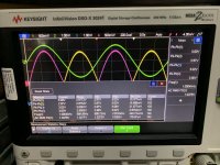
For PCM63, expected higher distortion at 0.006% for each SE channel. Balance is also about 0.006%. See photos.
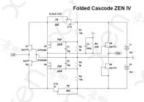
I have always been bothered by the ZEN IV's lack of PSRR and signal coupling caps.
I know it was a design choice in favour of simplicity.
So what is the price of getting rid of those ?
2 more MOSFETs for folded cascode, and 2 JFETs as CCS.
(The output buffer is of course optional.)
Apart from no cap in signal path and significantly improved PSRR, the input JFETs now see a very constant drain voltage.
That in turns means lower distortion.
Cheers,
Patrick
.
Attachments
Last edited:
HI Patrick,I have always been bothered by the ZEN IV's lack of PSRR and signal coupling caps.
I know it was a design choice in favour of simplicity.
So what is the price of getting rid of those ?
2 more MOSFETs for folded cascode, and 2 JFETs as CCS.
(The output buffer is of course optional.)
Apart from no cap in signal path and significantly improved PSRR, the input JFETs now see a very constant drain voltage.
That in turns means lower distortion.
Cheers,
Patrick
.
Thank you for sharing. Any measurement data to show how much better is the distortion? Very interesting!
Best Regards,
Spencer
Have not built yet. Need to get PCB made first.
(Most shops closed for CNY) 🙁
But I expect the simulations give you a good relative comparison between the two.
Patrick
PS I have changed rail voltages and resistor values to give the same 2Vrms out for 1mA current, for direct comparison.
(Most shops closed for CNY) 🙁
But I expect the simulations give you a good relative comparison between the two.
Patrick
PS I have changed rail voltages and resistor values to give the same 2Vrms out for 1mA current, for direct comparison.
Attachments
Last edited:
HI Patrick, I cannot read the ASC file! What program is required?
I use Breadboard to test the design. Just make sure it can work before spend money on PCB.

I use Breadboard to test the design. Just make sure it can work before spend money on PCB.
So quick ?
ASC file is LT Spice. If you run and press Ctrl L, you get FFT of the output.
And of course you can play with all different numbers.
How do you generate the signal current independent of any DAC ?
Cheers,
Patrick
ASC file is LT Spice. If you run and press Ctrl L, you get FFT of the output.
And of course you can play with all different numbers.
How do you generate the signal current independent of any DAC ?
Cheers,
Patrick
I did the bread board before I make the PCB.
Sorry not too sure what you mean by generate the signal current! I assume you talk about creating the input current source. I use the signal generator and in series with a 1k2 resistor. Then measure the Vrms at the input to estimate the input resistance of IV as well as the input current. Of course the signal generator input level must also be know.
Sorry not too sure what you mean by generate the signal current! I assume you talk about creating the input current source. I use the signal generator and in series with a 1k2 resistor. Then measure the Vrms at the input to estimate the input resistance of IV as well as the input current. Of course the signal generator input level must also be know.
That was what I meant.
I use sig gen at 2Vrms in series with 2.7k to simulate DAC current.
Patrick
I use sig gen at 2Vrms in series with 2.7k to simulate DAC current.
Patrick
I have always been bothered by the ZEN IV's lack of PSRR and signal coupling caps.
So what is the price of getting rid of those ?
2 more MOSFETs for folded cascode, and 2 JFETs as CCS.
.....
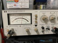
Here you go, first proto. Test pending.
Cheers,
Patrick


- Home
- Amplifiers
- Pass Labs
- Zen I/V Converter