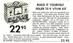
Evidentially it was offered in a factory wired form or kit form. I would like to find/buy the kit instructions and or schematic for this unit. I can't seem to find a schematic or any information other than it was made in 1950 was offered wired for $48 and in kit form for $22. Its quite nice for its age and with some rewiring and tweeking the 4 pots I would be able to bring it back to its former glory or at least good enough so I can use it on circuits in old radios and such. Any help would be appreciated. More than willing to buy the information that I need.


Last edited:
Might be a knock off of the Silver VOMAX, a very popular VOM of that time.
The magazines were full of ads for the Silver VOMAX,
The magazines were full of ads for the Silver VOMAX,
I bet the circuit is similar to the Heath VTVMs. I can't remember my tube multi-meter, but I think my AV VTVM had a single tube in it. Hmmm. what was thw rectifier? Been too many years.
In reality, other than nostalgia, a $20 Chinese DVM is a far better tool.
In reality, other than nostalgia, a $20 Chinese DVM is a far better tool.
In reality for most things a Chinese DVM works fine. I feel a tube volt, ohm meter is better when working with old radio's. I may be wrong.
Handier for nulling. I still have an old Micronda FET multimeter I keep for that. Sold my Heath VTVMs years ago. Bought a used Fluke for less.
As my old Tektronix scope failed, I just got a Hantek, but now I have to mod it for AC coupling. Digging though my old parts looking for a .1u, 600V cap. Darn, only have a 100.
As my old Tektronix scope failed, I just got a Hantek, but now I have to mod it for AC coupling. Digging though my old parts looking for a .1u, 600V cap. Darn, only have a 100.
My VTVMs use more modern tubes and a solid state rectifier for the power.
It is basically a resistor string attached to the range switch. A 6AL5 type rectifier to turn measured AC into DC. The actual measuring circuit is two triodes forming a differential pair. The meter goes across the anodes, if I recall correctly. To measure resistance a 1.5 volt C cell is placed across the 1.5 volt range through a resistor. The value of the resistor is the same as what the midpoint of that resistance range show.
So basically any VTVM schematic will get you started.
You of course will need a multimeter of some type to get started. First you check the input voltage divider string to be sure all the resistors are good. The total value of the string should be 10 megohms.
Just for normal age I would replace the power supply capacitor. It most likely is a can type containing two or three sections. To keep the look the same, carefully pry open the bottom of the can and throw out the mess in there. Then you can fit in modern electrolytic capacitors to give you the values stamped on the can.
Of course you will want to test the tubes. If possible replace the two (or dual) triodes with ones that have close to the same gain. There will of course be a balance variable resistor control and be sure to clean the sliding contact and then use a separate drop of control lubricant. Do not try an all in one spray.
There really isn’t much in the way of circuitry inside. Lots of parts to give you ranges, but simple circuits.
Here is a typical schematic, your will be almost the same.
vtvm article
https://lazyelectrons.wordpress.com...vtvm-vacuum-tube-volt-meter-repair-n-restore/
Last edited:
I've downloaded about 60 meg of meter schematics none of which are even close to the Feiler unit.My VTVMs use more modern tubes and a solid state rectifier for the power.
It is basically a resistor string attached to the range switch. A 6AL5 type rectifier to turn measured AC into DC. The actual measuring circuit is two triodes forming a differential pair. The meter goes across the anodes, if I recall correctly. To measure resistance a 1.5 volt C cell is placed across the 1.5 volt range through a resistor. The value of the resistor is the same as what the midpoint of that resistance range show.
So basically any VTVM schematic will get you started.
You of course will need a multimeter of some type to get started. First you check the input voltage divider string to be sure all the resistors are good. The total value of the string should be 10 megohms.
Just for normal age I would replace the power supply capacitor. It most likely is a can type containing two or three sections. To keep the look the same, carefully pry open the bottom of the can and throw out the mess in there. Then you can fit in modern electrolytic capacitors to give you the values stamped on the can.
Of course you will want to test the tubes. If possible replace the two (or dual) triodes with ones that have close to the same gain. There will of course be a balance variable resistor control and be sure to clean the sliding contact and then use a separate drop of control lubricant. Do not try an all in one spray.
There really isn’t much in the way of circuitry inside. Lots of parts to give you ranges, but simple circuits.
Here is a typical schematic, your will be almost the same.
vtvm article
https://lazyelectrons.wordpress.com...vtvm-vacuum-tube-volt-meter-repair-n-restore/
Then next up is to draw your own schematic. Pretty sure the power supply and voltage divider are pretty simple.I've downloaded about 60 meg of meter schematics none of which are even close to the Feiler unit.
I have a EICO 221 which is in the rebuild process because it was put together by someone who couldn't follow the wiring diagram. Its not even remotely similar to the Feiler.Have you look at this one EICO 221 which was sold as kit too at that time (1950s)?
I am in the process of trying to draw the schematic in my limited free time. Being this was also a kit unit a factory schematic along with the calibration information would make my life easier.
Eico 221 Schematic & Book here-I have a EICO 221 which is in the rebuild process because it was put together by someone who couldn't follow the wiring diagram. Its not even remotely similar to the Feiler.
I am in the process of trying to draw the schematic in my limited free time. Being this was also a kit unit a factory schematic along with the calibration information would make my life easier.
https://nvhrbiblio.nl/schema/Eico_221.pdf
ts-3a not sure if it's even close to yours.
http://bama.edebris.com/manuals/feiler/ts-3a/
Oops. Opened the schematic and it says stethoscope?
I managed to draw it the way it was wired.
No idea how to calibrate it for ohms as two controls effect it. Took a guess on the value of the DC probe resistor at 15meg.

No idea how to calibrate it for ohms as two controls effect it. Took a guess on the value of the DC probe resistor at 15meg.
Updated and finished schematic. I thought I was done when I posted the above schematic but in looking I had forgotten a few things. The schematic I am posting is of the working unit. It is surprising how good it works when its wired correctly and missing resistors are once again put into the circuit.
Attachments
- Home
- Amplifiers
- Tubes / Valves
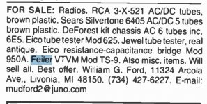
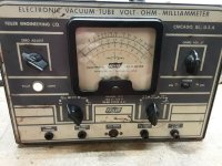
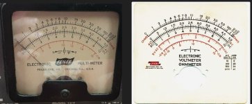
- Looking to repair a Feiler TS-9 Electronic Vacuum tube Volt-Ohm-Milliammeter