Then the filaments are the next suspect.Oh I see what your saying. That's the choke under the power switch, the outputs are in the back on the other side of the can cap
The ripple on the 47uF is probably normal, and the ripple on the 220uF should be small.
Yeah after the tubes get replaced I'll rectify one of the heaters to the 2a3's and go from there. I already tried doing a virtual center tap on one but it did nothing.Then the filaments are the next suspect.
The ripple on the 47uF is probably normal, and the ripple on the 220uF should be small.
Have you tried with DC on the 2A3 filaments? That's a rather obvious hum injection spot in a DHT amp.
Tom
Tom
I ended up rewiring the amp because I thought the hum might be heater related being it's 60hz but it didn't help anything. View attachment 1011039
1.) If the first HV capacitor is in the left (under the power transformer), the most "dirty" connection it's negative pole, so NEVER connect there anything, that wiring to second HV capacitor negative pole! The the second capacitor negative is the "ground bus" beginning point.
2.) The HV secondary CT point must be connected directly to first capacitor negative pole (sometimes via fuse)!
3.) The rectifier tubes output (even via resistors) must be connected directly to the first capacitor positive pole (and the choke "input" too). This wires from rectifiers usually the possible source of hum!
4.) Is really, that choke "output" connected to mA meter? It's a yoke!
5.) In good designs, the rectifier, the first HV capacitor, the choke and the second HV capacitor as close to each other as possible, with short wirings, which are not close another wiring.
So do you think I should put a switch in to bypass the mA meter when I'm not monitoring the current draw? The rest of what you said is over my head. I'm a picture kind of guy.1.) If the first HV capacitor is in the left (under the power transformer), the most "dirty" connection it's negative pole, so NEVER connect there anything, that wiring to second HV capacitor negative pole! The the second capacitor negative is the "ground bus" beginning point.
2.) The HV secondary CT point must be connected directly to first capacitor negative pole (sometimes via fuse)!
3.) The rectifier tubes output (even via resistors) must be connected directly to the first capacitor positive pole (and the choke "input" too). This wires from rectifiers usually the possible source of hum!
4.) Is really, that choke "output" connected to mA meter? It's a yoke!
5.) In good designs, the rectifier, the first HV capacitor, the choke and the second HV capacitor as close to each other as possible, with short wirings, which are not close another wiring.
I'm just learning how this stuff works. When I rewired it I just put everything the way it was just cleaned up. Are you saying I should put the center tap from the transformer to the negative on the cap right beside the transformer?1.) If the first HV capacitor is in the left (under the power transformer), the most "dirty" connection it's negative pole, so NEVER connect there anything, that wiring to second HV capacitor negative pole! The the second capacitor negative is the "ground bus" beginning point.
2.) The HV secondary CT point must be connected directly to first capacitor negative pole (sometimes via fuse)!
3.) The rectifier tubes output (even via resistors) must be connected directly to the first capacitor positive pole (and the choke "input" too). This wires from rectifiers usually the possible source of hum!
4.) Is really, that choke "output" connected to mA meter? It's a yoke!
5.) In good designs, the rectifier, the first HV capacitor, the choke and the second HV capacitor as close to each other as possible, with short wirings, which are not close another wiring.
It's risky to have a switch connected to the B+ voltage. Even the mA meter itself may not have adequateSo do you think I should put a switch in to bypass the mA meter when I'm not monitoring the current draw?
isolation for this connection in the amplifier.
I'll just take it out of the circuit then. Looks like I'm going to be rewiring this again.It's risky to have a switch connected to the B+ voltage. Even the mA meter itself may not have adequate
isolation for this connection in the amplifier.
I know I need to change something. I measured 15.9v AC on the B+but at the terminals of the large cap next to the transformer I get 50mv AC. Something is backwards here. That still doesn't address my problem though. If it was noise from the B+ it would be 120hz not 60hz.
Last edited:
Not surprising if the 15V ripple is on the 47uF, and 50mV ripple is on the 270uF. That's to be expected.
I fully agree with euro21. Attached a drawing to make the power supply cable routing clear.
Connect the rest of your amplifier to the points marked hv- and hv+.
It prevents hum coupling through magnetic fields and through the common gnd-bus.

Connect the rest of your amplifier to the points marked hv- and hv+.
It prevents hum coupling through magnetic fields and through the common gnd-bus.
Thank you. I'm not sure how to determine what side is the outside winding of the choke is though. Can't see anything from the outside.I fully agree with euro21. Attached a drawing to make the power supply cable routing clear.
Connect the rest of your amplifier to the points marked hv- and hv+.
It prevents hum coupling through magnetic fields and through the common gnd-bus.
View attachment 1011121
I'm a bit puzzled about your schematic.Better schematic pic.View attachment 1011036
Compared to the original schematic, your amplifier uses two 5Z3P's instead of one. It's not clear to me how you connected them exactly. Completely paralleled? Or each 5Z3P paralleled, and the two forming a full-wave rectifier? Or are you only using half of each 5Z3P, and than the two form a full-wave rectifier (that is what your schematic seems to show)?
But what strikes me the most are the values of the resistors between the 5Z3P's and the first capacitor (47 uF). In the original schematic (see post #2) these are three 10 Ohm resistors paralleled, making 3.3 Ohm in total. But in your amplifier there are two 15K resistors paralleled, making 7K5 in total. This doesn't seem to be a mistake in your schematic since these two 15K resistors are visible on the picture of your amplifier in post #9, although I'm not sure if the way in which they are connected is exactly like in your schematic.
If the OP could fit a 50R 2W wirewound potentiometer across the filaments for 'humbucking', instead of the two 22Rs there at the moment, that is how AC hum is minimised on vintage equipment.Then the filaments are the next suspect.
The ripple on the 47uF is probably normal, and the ripple on the 220uF should be small.
Nowadays it is not a big overhead to fit DC heating, so that could be the best bet?
Looks very neat under there!
The ground bus should be connected as shown (green), with part shown in yellow removed. Transformer center-tap direct to first cap so that its ripple current isn't flowing in the rest of the ground bus. Insulated wire for green ground connection - it's crossing other wires and terminls; should be kept short. If this is not your biggest hum problem, it will be more obvious when you do fix it!
Attachments
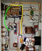
So then I make that cap the star ground point?The ground bus should be connected as shown (green), with part shown in yellow removed. Transformer center-tap direct to first cap so that its ripple current isn't flowing in the rest of the ground bus. Insulated wire for green ground connection - it's crossing other wires and terminls; should be kept short. If this is not your biggest hum problem, it will be more obvious when you do fix it!
You don't have a star ground - there is no "star point". Keep AC currents out of the chassis, and out of the ground bus, and grounding of everything else becomes non-critical. That first cap caries huge pulses of ripple current. Look at any vintage amp - they connected the transformer or bridge rectifier directly to the first power supply cap, and grounded everything else wherever it was convenient. And there was no hum, even from the phono preamp, which can be tough to get quiet.
Only for 120Hz hum.Keep AC currents out of the chassis, and out of the ground bus, and grounding of everything else becomes non-critical.
Also must remove the connection from loudspeaker terminals negative point to first cap negative !The ground bus should be connected as shown (green), with part shown in yellow removed.
Instead of it try connecting individual thin wires (there are no current, it's only for safety operation if OPT primary-secondary insulation damaged) from loudspeaker terminals negative points to ground bus (for example at second cap negative pole).
The other -safety- problem, that there are no fuse in HV part. I usually use it between HV CT point and first cap negative pole.
- Home
- Amplifiers
- Tubes / Valves
- A/C voltage on B+