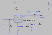
I´ve built a 3A5 preamp:


But what I do not completly understand is the Gyrator.
If I set the voltge (Anode) to about 100v,the current through the tube halves is 10mA 20mA per tube,maybe a little high.
And if I set the current to 5mA /triode ,10ma per tube.The voltage is about 60-65 v at anode.
The question is how do I set it?
By the way This one is microphonic....
The "gyrator" will set the plate voltage. From there you will need to adjust the bias voltage to set the current.
I've used the same board from aliexpress, with the same schematic as the output stage for a DAC - it sounds excellent in that role. The board parallels both triodes, I have mine running at 10mA per valve and ended up with about 90V or so at the anode.
Well at 10mA per valve I am having about 60v
Theres only 1 pot on the board so how can I set the current. The pot sets the voltage.
Theres only 1 pot on the board so how can I set the current. The pot sets the voltage.
Information like this is published in the tube's data sheet.If I ask like this,how much current is it safe to run throgh the 3A5?
Current is only one factor that needs to be taken into account. Dissipation is what you need to check, which is the current multiplied by the voltage across the tube. Here's the data sheet. It lists maximum plate dissipation of 0.5w when used for audio.
"Typical Operating Conditions" lists a combination of 90v at 3.7mA which produces a dissipation of 0.33w.
https://tubedata.edebris.com/sheets/127/3/3A5.pdf
Its strange thatt I dont get the same reading as you do..
Did you use this resistor at the filament?

Did you use this resistor at the filament?
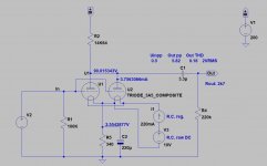
The bias method in #1 post and in #7 russian picture are different.
The first is filament bias.

The later is "classical" cathode bias.

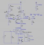
BTW as I wrote another topic, the Rod Coleman regulator parts and the raw supply MUST be "ground independent"!
The raw supply voltage at least: filament resistor voltage (if it is filament biased)+ tube filament voltage + 5V!
The first is filament bias.

The later is "classical" cathode bias.

BTW as I wrote another topic, the Rod Coleman regulator parts and the raw supply MUST be "ground independent"!
The raw supply voltage at least: filament resistor voltage (if it is filament biased)+ tube filament voltage + 5V!
I used that in post 7.The bias method in #1 post and in #7 russian picture are different.
I use 10 ohm now,but as I get so high current (60v/10mA) maybe I should use a larger resistor to get 90v/10mA.
How do I calculate the resistor?
But I dont use an elyt over the resistor,should I?
How do I calculate the resistor?
But I dont use an elyt over the resistor,should I?
In the #7 post the bias method is cathode bias: the cathode current (about 10mA) flowing trough the cathode resistor, generating bias voltage.I used that in post 7.
After you get it working ok - have a look again at filament bias from your first post and then you can see which way you prefer it.
Be very careful with the heaters on the 3a5 - they will not withstand much voltage, so be very careful when you are connecting the filament reg for the first time - voice of someone who burnt one out in a stupid moment!
Be very careful with the heaters on the 3a5 - they will not withstand much voltage, so be very careful when you are connecting the filament reg for the first time - voice of someone who burnt one out in a stupid moment!
Watching with interest - I have a couple of Moglia's Gyrator boards, some DHT filament supplies and a few 3A5s for a similar build. I have to finish a 2P29L version first thouh!
Run it as an output stage for the AD1862 DAC..... 500R IV resistor. You won' be sorry.Watching with interest - I have a couple of Moglia's Gyrator boards, some DHT filament supplies and a few 3A5s for a similar build. I have to finish a 2P29L version first thouh!
Now, there's a thought. Hmmm.Run it as an output stage for the AD1862 DAC..... 500R IV resistor. You won' be sorry.
- Home
- Amplifiers
- Tubes / Valves
- I´ve built a 3A5 preamp
