One thing is that one tube is constantly making a noise,it is not loud but I can hear it inbetween songs.
Is it the tube it self or what?
Ofcoarse it is easy to swap the tube and se.....
Is it the tube it self or what?
Ofcoarse it is easy to swap the tube and se.....
Is this microphonic?
Try to lightly knocking the tube.
Try to using grid stopper (few hundred Ohm carbon comp resistor) on both grid.
Try to lightly knocking the tube.
Try to using grid stopper (few hundred Ohm carbon comp resistor) on both grid.
3a5 are very microphonic in general. It can be hard enough to distinguish hum from grounding, with hum from filament noise, with hum from mechanical vibration coupling to the valves.
If you have a transformer on the unit that vibrates for example, you will hear it amplified. One way to test that is to touch the tubes and it usually damps or changes the noise. Be careful with the voltage to the heaters - if you go past 1.6V you will burn out the heaters very quickly. Try them with a D-cell and see if the noise is gone, and you know then if its the heater supplies.
Another thing I found out is that if you are using a transformer with multiple windings - eg 150V for the B+ and then 2 x 12V for the heaters, you can get hum in the heaters. Use separate transformers and no hum. You could temporarily drop the black pcb from the chassis and just leave it sitting on its wires and see does that change it.
Yes its very microphonic.
But the noise does not Come from that.
I have 2 transformers.
I Will try another tube tomorrow.
But the noise does not Come from that.
I have 2 transformers.
I Will try another tube tomorrow.
If the noise not hum type, try to temporarily RFI shielding tube with grounded aluminium folie.
I have in my collection ancient DHT tubes which tend to working as AM radio and cellular telephone detector. :-(
p.s. flicker noise is annoying phenomenon of old tubes. Sometimes without any sign the well working tube starts sizzling.
p.s. 2: are you "AC grounded" filament FT (pin 4) with 0.1uF capacitor, or it's a "cathode"?
Last edited:
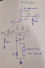
And I take it you are measuring the heater voltage ~1.3-1.4V from pin 4 to pins 1/7 which are tied together?
Which type and value of resistor?I use a Rod Coleman regulator for filament,and a resistor from pin 4 to grund.
380 ohm is way too high I think for the filament bias. The schematics on Bartola website say 10ohm 5W - and this is what I have used on a few builds.
Don't forget to turn down everything before you power back up with new values!
Don't forget to turn down everything before you power back up with new values!
If you build as I shows in #11 post, it's not filament bias method.
It's simple cathode bias, and must be use cathode resistor decoupling capacitor.
It's simple cathode bias, and must be use cathode resistor decoupling capacitor.
Can I check:
have you paralleled both triodes in each valve? So the anode of the gyrator is going to pins 2 and 6?
Pins 1 and 7 are joined together, then to the 10r resistor, and the other side of this resistor is connected to ground?
The positive of the Coleman regulator is connected to pin 4
The negative of the Coleman regulator is connected to ground
Yes its connected as described.
Except th filament is not connected to grund it is floating.
The resistor is connected to grund.
Rod Coleman descrives it so in his descriptions.
Except th filament is not connected to grund it is floating.
The resistor is connected to grund.
Rod Coleman descrives it so in his descriptions.
Like this:
Pins 1&7---10ohm resistor----ground
It looks like you have it arranged correctly other than the filament bias resistor is too high. What is the voltage between pin 4 and pin 3/5?
Pins 1&7---10ohm resistor----ground
It looks like you have it arranged correctly other than the filament bias resistor is too high. What is the voltage between pin 4 and pin 3/5?
- Home
- Amplifiers
- Tubes / Valves
- I´ve built a 3A5 preamp