I bought this chinese XH-M139 amp, based on the TPA3116D2.
Some people recommend it, some people had an unpleasing experience. It's a lottery.
Since I can't hear the 50th harmonic, it's great.
Except that it thumps exactly once a second. Not when turning on or off, the common complaint.
It starts after some time playing a song. When exactly? Seems random.
Seems to happen specially when my input volume is too low, either when my phone is low, or the volume knob on the board.
Raising the volume most of the times fixes it, but since I have neighbors, can't always do this...
Is there a permanent fix ? I hear the schematics for this board is all around
Here's a picture. The blue version. SOIC opamps:
https://encrypted-tbn0.gstatic.com/images?q=tbn:ANd9GcQW6TPJSnaxww4gkZFyDg9uY8wHIkYFqaGbTw&usqp=CAU
BIG CORRECTION !
When the OUTPUT volume is low, the problem occurs
(One of the knobs is for stereo output volume)
I was mistaken before because raising the input will, obviously, raise the output...
Now I cranked the input to the maximum volume, both on the phone and the input knob, and slowly raised the output volume until the second-wise thumps stop
I had a similar problem, after swapping the amp chip on known good boards I came to the conclusion that it's the board's fault in that particular case but i wasn't able to find the cause
Hello.
By Amp chip do you mean the NA5532? Or the TPA3116D2?
Because if I have to switch the TPA, then I can basically throw the whole board on the trash. ..
🙁
By Amp chip do you mean the NA5532? Or the TPA3116D2?
Because if I have to switch the TPA, then I can basically throw the whole board on the trash. ..
🙁
Please ignore my previous question.
At firts I understood that you took the chip from other boards and fixed yours
It's the contrary, right ? You took the chip from this faulty board and fixed another one, if I understood
At firts I understood that you took the chip from other boards and fixed yours
It's the contrary, right ? You took the chip from this faulty board and fixed another one, if I understood
Is it one both channels or only one channel? If on only one channel it is likely to be in the signal path, if on both channels it may be a supply issue or a control pin issue.
With your oscilloscope, can you see the "thumps" on the power (supply) line to the tpa3116 or the supply line to the NE5532?
What is the ripple frequency at all the tpa3116 outputs without input signal? (it is supposed to be close to 400KHz).
With your oscilloscope, can you see the "thumps" on the power (supply) line to the tpa3116 or the supply line to the NE5532?
What is the ripple frequency at all the tpa3116 outputs without input signal? (it is supposed to be close to 400KHz).
I'll verify all the items of your list. Might take a week.
I didn't pay attention before you asked. Now I did: the thumps occurr on the right channel. The left ? Completely mute !
Thank you for the assistance
I didn't pay attention before you asked. Now I did: the thumps occurr on the right channel. The left ? Completely mute !
Thank you for the assistance
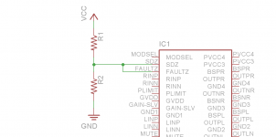
Using the oscilloscope, I found the thump pattern coming off the FAULTZ/SDZ node
(These two pinouts are connected)
This node receives 2.2V from a voltage divider (my supply is 12V)
Please see the attached picture
This same configuration is valid for Both the stereo channel and the sub channel (one TPA3116 for the stereo, and one for the sub)
Now:
I floated this FAULTZ node (don't know why it was connected to a voltage divider source in the first place, since it's an output according to the datasheet)
After floating this FAULTZ, the thump stopped and the stereo music too (muted).
The SUB CONTINUED PLAYING the song perfectly. They are clearly independent, no matter what volume.
If I briefly tap together (short) some ports, the music comes back, but:
- Temporarily, IF my input volume is low.
It stops playing anytime the singer lowers his voice. Only the sub keeps playing.
- Longer, IF my input volume is high. The stereo and sub keep playing. No thumps. All good. Too bad it goes mute when the song ends.
Turns out, I can't keep the volume high all the time. Much less keep tapping the circuit.
Analising this floated FAULTZ port with the oscilloscope again shows only low level noise.
Can I do something to fix it ?
Need more information ?
Attachments
Hello LucasBS,
do you fixed it already?
I bought an XM-139 and have a similar problem - thumbs on one channel and the other channel is muted. Scope and function generator are also available ...
do you fixed it already?
I bought an XM-139 and have a similar problem - thumbs on one channel and the other channel is muted. Scope and function generator are also available ...
Hello LucasBS,
do you fixed it already?
No fixing yet.
In fact, damaged it even further trying to fix this thing.
So I gave up.
It's there on my drawer, waiting for a solution.
Member
Joined 2018
LucasBS
How about removing the lower-side resistor (R2 in your schematic above)?Using the oscilloscope, I found the thump pattern coming off the FAULTZ/SDZ node
(These two pinouts are connected)
This node receives 2.2V from a voltage divider (my supply is 12V)
Hello LucasBS,
after some experiments my xh-m139 is operable, a solution seems to be possible.
Current status of my experiments:
- The heat sink is removed. -> The PCB is not bended (= reduced mechanical stress) and the capacitive coupling of the two amps is removed. Now the output power is limited by temperature of the chips. I'm looking for a different mechanical solution to fix the heat sink without bending the PCB. If the heat sink is connected to ground the capacitive coupling may be ignored.
- Unused outputs are terminated with a 4R7 power resistor. It should be checked if this is necessary.
- If the amps are connected to a linear regulated laboratory power supply @ 12V operation is o.k., I have tested some different switched mode power supplies to supply the module, some are o.k. some failed. There may be an interference of supply and amps. A decoupling network may solve this challenge but has to be designed and checked.
(...BS = Braunschweig ?)
Greetings from the baltic sea.
(...BS = Braunschweig ?)
Benetti Silva
Half italian, half brazilian
If the heat sink is connected to ground the capacitive coupling may be ignored.
This should be easy to do, right ?
I Don't have the board on my hand right now, so forgive me for the question, but: are you sure there are power (big) resistors on the output ?- Unused outputs are terminated with a 4R7 power resistor. It should be checked if this is necessary.
Judging by PICTURES I found on the internet I can only see capacitors and inductors.
If there ARE resistors, are they not part of an audio bandpass filter ?
I hope the results from your test are a coincidence, because it seems quite abusive/unreallistic from the amp developer to demand from their customers a super-filtered-super-expensive power supply.- If the amps are connected to a linear regulated laboratory power supply @ 12V operation is o.k., I have tested some different switched mode power supplies to supply the module, some are o.k. some failed. There may be an interference of supply and amps. A decoupling network may solve this challenge but has to be designed and checked.
But... this board has many capacitors on the input. They cannot create current, but I think they are good noise filters.
I remember removing the big ones for testing. No result.
Last edited:
after some experiments my xh-m139 is operable, a solution seems to be possible.
Klostery,
Could you try CyberPit's solution above ?
I'll be far from home for a good while.
LucasBS
How about removing the lower-side resistor (R2 in your schematic above)?
I have an XH-A305 amplifier board, which basically seem to be a bluetooth equipped version of the XH-M139. While modding it I managed to damage a few capacitors. Since they are ceramic SMD capacitors they don't have any markings which means that I don't know what to replace them with.
I have search around for schematics, I even contacted a seller in China who claimed to have the datasheet, but so far I haven't been able to find anything.
Since the 305 and 139 are so similar I tried to see if I could maybe find a datasheet or schematics for that version, which lead me to this thread. While I haven't been able to find anything myself, I was hoping that maybe someone else here might have.
Does anyone have the schematics for the XH-A139 (or even better the XH-A305) that they would be willing to share with me? Thank you in advance!
XH-M139 amp, based on the TPA3116D2. [...] I hear the schematics for this board is all around
Member
Joined 2018
Hi Papperskatt-San,
There are two versions XH-M139 board exists. One is a through-hole type and the other is an SMD type. But its circuity seems to be the same.
Here's my XH-M139 modification web page (through-hole type)
The XH-A305 has 2 more Op-amps than XH-M139. Perhaps it adds mixing buffers for the sub-woofer channel. (Not sure)
So the XH-A305 schematic will be different from XH-M139...
CyberPit
- Home
- Amplifiers
- Class D
- XH-M139 amp with constant thumps