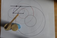
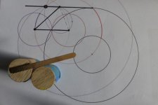
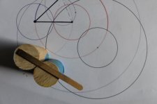
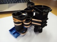
I think I know where alighiszem's idea came from. He thought the guide was a slot so the link had the room to move up and down. Please see the model. No. we are still in the world of mathematics. The rear guide should not have any room to wiggle in a conceptualized world. The guide is not realized yet. What will it be in reality? I don't know. The guide will be a complicated one. This is why I kept saying that Bon's geometry will work but it is complicated in reality. It may be so complicated that it is not efficient enough.

Last edited:
Thank you for trying to understand what I wrote.I think I know where alighiszem's idea came from. He thought the guide was a slot so the link had the room to move up and down. Please see the model. No. we are still in the world of mathematics. The rear guide should not have any room to wiggle in a conceptualized world. The guide is not realized yet. What will it be in reality? I don't know. The guide will be a complicated one. This is why I kept saying that Bon's geometry will work but it is complicated in reality. It may be so complicated that it is not efficient enough.
View attachment 1008454
No, I did not think that the guide is a slot. But the tonearm is capable of making this movement, so it is not constrained to the Thales circle.
You proved it.
My drawing might be inaccurate, but this is not the point. Try to put the stylus not on the Thales circle, with the same dimensions.The drawing you did was wrong. Both red and green instances in your drawing don't exist in Bon's geometry. You drew wrong conclusion from an inaccurate drawing. The drawing below is a correct one. All three X's (black, red, green) should be equal. All three Y's (black, red, green) should be equal.
View attachment 1008434
It is possible.
You were talking about an actual device that allows the movements up and down by itself such as a slot or similar device. In my mind, it is just a conceptualized device that does not allow up and down movements by itself. So, in my mind, Bon's geometry is fine. It is a completely different matter if such a conceptualized device can be realized.Thank you for trying to understand what I wrote.
No, I did not think that the guide is a slot. But the tonearm is capable of making this movement, so it is not constrained to the Thales circle.
You proved it.
Your 6B tonearm can move only on the Thales circle (within a certain tolerance). Without destroying the tonearm you cannot put the stylus elsewhere.
Bon's tonearm can move in a wide band around the Thales circle. What force would it make to stay on the Thales circle?
Bon's tonearm can move in a wide band around the Thales circle. What force would it make to stay on the Thales circle?
I don't know because I don't know what kind of device to control the movements. If you look at the geometry of Reed 5T, you can't tell too much. It is the same case here.What force would it make to stay on the Thales circle?
The Reed 5T is a servo control tangential tracking tonearm. Instead of parallel tracking it pivots and the top part of the arm has a laser beaming towards the Thales locus and servo control movement comforming to the Birch geometry. Check video.If you look at the geometry of Reed 5T, you can't tell too much.
I've been playing with my notorious models again.
It may be that a construction possibility shows up in the video in Bon's post 243. The genius of Bon's geometry is the it frees the control arm pivot point. If two circular cams are connected using something similar to 2wice's arrangement, the control arm follows the necessary path. I think the side force on the stylus is enough to make this happen. Alighiszem is right that Bon's arm needs a constraint to turn geometry into a working arm. This arrangement provides that. It might be that a connection between the centers of the two cams would work, but at the cost of more bearings and noise.
Jim,
Your magnet controlled arm is an interesting new angle - sorry - on the classic Birch/Thales arm and will probably work quite well if built carefully. Magnet theory and my experience both tell me you don't need, or even want, two magnets and the bar magnet will cause problems for the pivot bearing unless it's full ceramic, not just hybrid. Beyond that, the geometry of the stylus, the outer control arm bearing, and the guide arm bearing insures the magnet and the attractor stay aligned. I tried something similar with the first Birch/Thales I built. It worked fairly well, but my arrangement was unstable and caused stress. Your's is better.
Doug


.
It may be that a construction possibility shows up in the video in Bon's post 243. The genius of Bon's geometry is the it frees the control arm pivot point. If two circular cams are connected using something similar to 2wice's arrangement, the control arm follows the necessary path. I think the side force on the stylus is enough to make this happen. Alighiszem is right that Bon's arm needs a constraint to turn geometry into a working arm. This arrangement provides that. It might be that a connection between the centers of the two cams would work, but at the cost of more bearings and noise.
Jim,
Your magnet controlled arm is an interesting new angle - sorry - on the classic Birch/Thales arm and will probably work quite well if built carefully. Magnet theory and my experience both tell me you don't need, or even want, two magnets and the bar magnet will cause problems for the pivot bearing unless it's full ceramic, not just hybrid. Beyond that, the geometry of the stylus, the outer control arm bearing, and the guide arm bearing insures the magnet and the attractor stay aligned. I tried something similar with the first Birch/Thales I built. It worked fairly well, but my arrangement was unstable and caused stress. Your's is better.
Doug


.
I understand how the 5T works. What I was saying is I can't tell by just looking at Bon's diagram to tell how the geometry works. It is the same for 5T. If I just look at the following diagram, it is a universal Birch-style arm. It doesn't work at all. There is no secondary guide. The arm is not constrained at all. But 5T is a working arm. A lot of detail don't reflect on the diagram. I can't tell too much of it from the diagram for 5T just the same as I look at Bon's diagram. There is not much that can be told until Bon's geometry is implemented.The Reed 5T is a servo control tangential tracking tonearm. Instead of parallel tracking it pivots and the top part of the arm has a laser beaming towards the Thales locus and servo control movement comforming to the Birch geometry. Check video.
Doug,Your magnet controlled arm is an interesting new angle - sorry - on the classic Birch/Thales arm and will probably work quite well if built carefully. Magnet theory and my experience both tell me you don't need, or even want, two magnets and the bar magnet will cause problems for the pivot bearing unless it's full ceramic, not just hybrid. Beyond that, the geometry of the stylus, the outer control arm bearing, and the guide arm bearing insures the magnet and the attractor stay aligned. I tried something similar with the first Birch/Thales I built. It worked fairly well, but my arrangement was unstable and caused stress. Your's is better.
Doug
The ball bearing has to be a ceramic one. Otherwise, it won't work.
I still believe that two magnets may work better. In my proposal, the width of the magnets is only 2 mm. I may have to try it to know if it works or not.
I believe the arm I proposed here can work. However, its geometry needs to be revised in order to reduce tracking errors and to solve the armrest problem. In my mind, a PT arm must utilize pivot bearings. Otherwise, it doesn't make too much sense to me. Of course, I am saying that there is no chance for non-pivot PT arms.
Jim
I am very impressed by Bon's study about PT arms. The 1st video reveals the relationship between the elements although implementation isn't an easy task. It is a true zero tracking errors geometry.

The 2nd video is this one. He discovered Limacoms. It confirms my belief that expanded movements reduce tracking errors.

Based on his study, I revised my 6C geometry again. It is 6D now. The tracking errors are reduced even more in 6D because of expanding secondary Birch circle. But I still don't have a plan to build 6D yet.


The 2nd video is this one. He discovered Limacoms. It confirms my belief that expanded movements reduce tracking errors.
Based on his study, I revised my 6C geometry again. It is 6D now. The tracking errors are reduced even more in 6D because of expanding secondary Birch circle. But I still don't have a plan to build 6D yet.
Thank you for the acknowledgement. Your proposal solves the problem.Alighiszem is right that Bon's arm needs a constraint to turn geometry into a working arm. This arrangement provides that. It might be that a connection between the centers of the two cams would work, but at the cost of more bearings and noise.
.
You're welcome. As drawn, Bon's arm just looked a little floppy and I was convinced what you saw was real. I'm sure there are other solutions.Thank you for the acknowledgement. Your proposal solves the problem.
I missed something in the cam proposal - everything is too close to the platter so unless the cams can be moved, it won't work. The stationary cam needs to be moved away from the platter edge, part of it removed, and the rolling cam needs to be reduced to something like a triangle with the pivot at the apex so it doesn't foul the arm pivot.
The sliding arm pivot always seemed less than optimal then Jim came up with his magnet guide. I think that might handle that nicely.
I hope everybody is enjoying the holidays.
Doug
Alighiszem,Your tonearm's movement is not constrained enough, it can move anywhere, not only on the Thales circle. ........
Your animation does not prove that your tonearm is sufficiently constrained.
you are correct. I withdraw my comments in posts #269 , #274 .
Happy New Year.
The non tangential geometry is easily excluded by addition of a secondary circle path guide as shown in the first video below. I have previously considered this configuration in post #218, but looked past it because of concerns of extra complexity and friction. I propose calling this the parallelogram circle guide.
There is something else to consider. The tangential geometry describes the steady state with the stylus sitting on the Thales circle on a stationary disc.
As has been pointed out by Alighiszem, the single guide geometry does not exclude other non-tangential stylus positions.
I conjecture that with a rotating disc, the stylus drag and skating force makes the single guide non-tangential geometry unstable and the tonearm re-aligns to the single guide tangential geometry. Experiments with a working model suggests something like this happens.
In the second video, I purposely mis-align the stylus position on a grooveless acrylic disc (from the 1:50 mark). It can be observed how the tonearm re-adjusts by skating to the tangential geometry in every instance.
The tangential geometry is maintained when tracking a grooved disc. The dark line across the headshell in line with the stylus, points directly towards the disc centre as the tonearm tracks the groove.
In any case, the parallelogram guide geometry will result in a properly constrained tangential tonearm geometry, albeit requiring even more challenging engineering solutions. I am confident there is the talent available here.
Hi Jim.What I was saying is I can't tell by just looking at Bon's diagram to tell how the geometry works.
Maybe the full video showing the rolling circles geometry will shed some light. I chose lengths that give rolling circles of Thales diameter and 1/2 Thales diameter. This is just for simplicity and any lengths can be substituted with the appropriate adjustments. Hope this helps.
I am sorry having to say that this arrangement is also not sufficiently constrained.Hi Jim.
Maybe the full video showing the rolling circles geometry will shed some light. I chose lengths that give rolling circles of Thales diameter and 1/2 Thales diameter. This is just for simplicity and any lengths can be substituted with the appropriate adjustments. Hope this helps.
There is no mechanical connection between the position of the rolling pivot A and the angle alpha.
In the second video, I purposely mis-align the stylus position on a grooveless acrylic disc (from the 1:50 mark). It can be observed how the tonearm re-adjusts by skating to the tangential geometry in every instance.
The tonearm does not align itself to the tangential geometry. It remains in a position on which the sum of all forces to which it is subject (vinyl friction, skating, friction of the bearings) is zero.
The two cam guides are concentric circles, the rigid link joining them is of fixed length, the difference between the radii of the concentric circles. Point A can only move if angle alpha changes.I am sorry having to say that this arrangement is also not sufficiently constrained.
There is no mechanical connection between the position of the rolling pivot A and the angle alpha.
"X" is the true pivot point. Do you plan to have a linkage connecting from X to the red part of the parallelogram? X is locaed in the platter area which makes it awkward to implement. If X has a linkage to the paralleogram, it seems, everything should fall into place...


Why could alpha not change without point A moving?The two cam guides are concentric circles, the rigid link joining them is of fixed length, the difference between the radii of the concentric circles. Point A can only move if angle alpha changes.
- Home
- Source & Line
- Analogue Source
- A tangential tracking pivoting tonearm