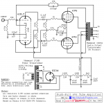
OK, hang on...now the concept is getting a little clearer... Based upon the schematic below, I see how the output tube is getting its bias voltage from the halves of the transformer. However, this XFMR has another set of primary legs to ingest the output tubes HV audio signal. Its different from the other schematics I am looking at, but I get the concept now of "powering the output stage." Thanks 50AE for that.
However, I guess I am still struggling with how the DC-to-CT leg induces a suitable DC voltage for each Output plate. What are the mechanics that make this possible?
However, I guess I am still struggling with how the DC-to-CT leg induces a suitable DC voltage for each Output plate. What are the mechanics that make this possible?
Attachments
The tube (+ transformer) as an amplification active stage needs to be fed with energy in the form of DC voltage.
It modulates this voltage into an AC voltage. The frequencies and amplitude of this "modulated DC power supply" are dictated by the input of this stage.
You just need to check the basics of how amplifiers work.
The transformer is mainly there to transform a higher voltage, impedance and lower current into the other way around at the secondary.
The circuit schematic is missing a cathode resistor to ground for the 6SL7 phase inverter stage. A 1.8 to 2.2 kohm resistor connected in // with the 100 mFd/16 v capacitor should be fitted. The 6V6 O/P stage derives its' bias from the shared 250 ohm cathode resistor to answer thw question from post #21.
VaNarn, thank you for the proof-reading. I'll note that for sure. And 50AE, I assure you I am across the basics of amplification as it applies to tubes and transistors. By no means proficient, but learning. I'm still not focusing the question correctly. So what about this...
Lets say we had a normal CT power supply transformer. Ex. 120vac in, 240-0-240 out, and then we fed that signal into the output of an identical transformer. The resulting voltage (now measured at the input because the connections are reversed with regards to the first XFMR) should be 120vac, correct? So as far as transformers go, it doesn't get much simpler. We have doubled the voltage, halved the current, and gone back again.
Now, with regards to an amplifier's output section, I completely understand the need for Plate voltage. I guess I never looked close enough to note where (for output tubes) it was derived. Now I know....From the output XFMR.
So with that in mind, please walk me through what is happening in the schematic below with regards to DC entering one leg of the XFMR, and the output tube's waveform entering on the second. In my mind, I would expect the Output XFMR input to be the tube's output on one leg, and chassis ground to the other. Like the example above (well, sort of). For such a primitive amp, I am struggling to understand this output/power supply. I have no interest in progressing until I have this sorted in my head.
And I very much appreciate everyone who has taken time to help. I don't mean to be a burden with such basic topics, and will understand someone pointing me to a book or site that better describes what I am asking about.
Thanks!
Attachments

Basically the transformer primary is the "special" plate resistor for the output tube ... if you understand how the first two small tubes work .
There are of course old transistor circuits just the same ...
There are of course old transistor circuits just the same ...
May I ask a “new” question, please, of the experts here. I am a novice in transformer winding and still gathering tools and parts to make my first attempt to build an OT.
The question is is about optimum interleaving. I read that more interleaving is better, but that it also increases the possibility of mistakes as well as difficulty in winding. How does one go about determining the optimum configuration?
The question is is about optimum interleaving. I read that more interleaving is better, but that it also increases the possibility of mistakes as well as difficulty in winding. How does one go about determining the optimum configuration?
Most main transformer parameters such as output power, primary impedance, core material choice, style of high-frequency behavior will dictate the style of interleaving. It's a bit of a complex situation for a beginner.
The balance of audio transformer parasitics Cp, Cs and Ls come together forming a HF filter that will dictate your roll-off behavior. Every manufacturer has its own "style", meaning different Qs, phase and FR relations.
I dare not to say which recipe is optimal and I have developed my personal style of distributing these as well. Keep in mind the beavior of the resulting filter is also dependent of the load. Most manufacturers test FR on resistor load, but it is normal for HF response to vary with different speakers.
Basic rule of thumb is:
Low interleaving is for high primary impedance and high Ra tubes.
High interleaving is for low primary impedance and low Ra tubes.
But it's up to you to decide "how much". If you wish to go in depth with this, you have to visit a few books first. I'd recommend Crowhurst stuff and RDH4 to begin with.
With going lower with interleaving, you're aiming for a higher Ls and lower Cs. For now we're leaving Cp alone.
Last edited:
This should help.Now, with regards to an amplifier's output section, I completely understand the need for Plate voltage. I guess I never looked close enough to note where (for output tubes) it was derived. Now I know....From the output XFMR.
http://www.valvewizard.co.uk/pp.html
Mutual inductance is a function of the magnetic flux shared by both primary and secondary windings. Any flux that is not mutually shared by both windings results in leakage inductance. When primary and secondary windings are more distant from each other, it may be easier for some of the flux to take a path through only one winding. Does that help?I’d like to understand why.
In a transformer, leakage inductance is dependent of the distance between primary and secondary layers.
Hi sir,
Can I know where can I buy the transformer Lamination?
I want to get the HiB M6 for self transformer use.
Thanks
Can I know where can I buy the transformer Lamination?
I want to get the HiB M6 for self transformer use.
Thanks
I cannot find the information on Edcor.Edcor used to sell laminations and bobbins.
Chers
Ian
Attachments

Have you ever built an interstage that uses dual split bobbins where the primary was wound across both chambers and one secondary was would on one of the chambers in the same direction as the primary but the second secondary was wound on the other chamber but spun in the opposite direction? Do you think that would give good push pull drive balance?Hi there tube enthusiasts,
I have designed, built and analyzed over 150 Audio transformers projects, consisting of mostly output, line-in, interstage transformers, chokes and power transformers. And I'm happily creating a Discord chat channel that will be based on Q&A on Electrical aspects on Transformers for audio purposes, where I will be happy to answer you a variety of answers related to this topic.
You can visit the channel via this link: https://discord.gg/FT26dQzywB
Just keep in mind I will be randomly available throughout different times of the day, 8 to 10PM CET Time zone.
Best regards,
Alexander.
Have you ever built an interstage that uses dual split bobbins where the primary was wound across both chambers and one secondary was would on one of the chambers in the same direction as the primary but the second secondary was wound on the other chamber but spun in the opposite direction? Do you think that would give good single ended to push pull drive balance?
Vacuum or pressure pot for potting? Mostly interested in power supply transformers and chokes but I suspect we don't want spurious vibrations in output transformers either. The SS side of the house forgets about chokes. So many modern transformers are not even dipped, let alone saturation potted.
Transformer design is way above my pay grade. I can't even do a realistic model in Spice. My hats off to those of you who can.
For line transformers, is our safe bet just to open the Jensen catalog?
Transformer design is way above my pay grade. I can't even do a realistic model in Spice. My hats off to those of you who can.
For line transformers, is our safe bet just to open the Jensen catalog?
Have you ever built an interstage that uses dual split bobbins where the primary was wound across both chambers and one secondary was would on one of the chambers in the same direction as the primary but the second secondary was wound on the other chamber but spun in the opposite direction? Do you think that would give good push pull drive balance?
It depends of the application. If will be to be used for a SE to PP, it will work, but no interleaving. Otherwise you'll need copper shielding for capacitance equalization. Primaries in parallel so that equal voltage gradient will be present on both halves. You have the freedom to reverse a half primary or secondary, your choice. You can choose the primary to secondary voltage gradients be the nearest to zero, meaning you will ground these layers. The transformer will become a 1:1+1. Primaries in parallel, secondaries in series.
(+) S1.. ..S6 (-)
...S2... ...S5...
...S3 CT--CT S4
----------------------
P3 out P3 out
..P2.. ...P2...
in P1 in P1
Vacuum or pressure pot for potting? Mostly interested in power supply transformers and chokes but I suspect we don't want spurious vibrations in output transformers either. The SS side of the house forgets about chokes. So many modern transformers are not even dipped, let alone saturation potted.
Transformer design is way above my pay grade. I can't even do a realistic model in Spice. My hats off to those of you who can.
For line transformers, is our safe bet just to open the Jensen catalog?
In power transformers and my experience, noise comes from two main sources:
1. Core laminations or cutting surfaces (c-cores) slamming against each other. C-cores most often need gluing for maximum silence, while EIs might benefit from vacuum potting. This has more often a low-pitched hum (100 to 120Hz), but can result in some higher frequencies buzzing as we..
2. Windings, especially with high pulse current when feeding a high C-input filter. Vacuum lacquer potting helps solving this, but potting does it even better. These often result in a higher frequency buzz.
Exactly, but I would think interleaving is still possible.It depends of the application. If will be to be used for a SE to PP, it will work, but no interleaving. Otherwise you'll need copper shielding for capacitance equalization. Primaries in parallel so that equal voltage gradient will be present on both halves. You have the freedom to reverse a half primary or secondary, your choice. You can choose the primary to secondary voltage gradients be the nearest to zero, meaning you will ground these layers. The transformer will become a 1:1+1. Primaries in parallel, secondaries in series.
(+) S1.. ..S6 (-)
...S2... ...S5...
...S3 CT--CT S4
----------------------
P3 out P3 out
..P2.. ...P2...
in P1 in P1
- Home
- Amplifiers
- Tubes / Valves
- Audio transformers chat channel.