It seems to me that your OLED is drawing too much current which brings down the voltage on Nano supply line, or you have a parasitic resistance somewhere along the power line.
1) Connect OLED to separate (LAB) 5V power supply and check how much current it draws.
2) When OLED is connected, is 2.02V consistent throughout the 5V line starting from 7805 regulator, or is there a voltage drop somewhere along the line? If you have 5V after the regulator and 2.02 at VCC on OLED, you have a resistance somewhere along the line.
I think you have problem on vcc oled
Do you mean that voltage on LED VCC supply line should be 5 VDC ?
It seems to me that your OLED is drawing too much current which brings down the voltage on Nano supply line, or you have a parasitic resistance somewhere along the power line.
1) Connect OLED to separate (LAB) 5V power supply and check how much current it draws.
2) When OLED is connected, is 2.02V consistent throughout the 5V line starting from 7805 regulator, or is there a voltage drop somewhere along the line? If you have 5V after the regulator and 2.02 at VCC on OLED, you have a resistance somewhere along the line.
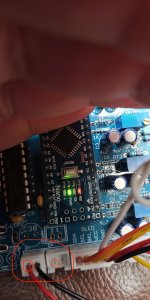
1-> The current of OLED power is 4.1mA
2-> When OLED connected the 2.02V DC is on terminal OLED VCC or main board point VCC. All regulators 7805 gives on output from power supply up to main board 5V DC.
Without schematic I`m "in dark forest at night"....
From where VCC to OLED is powered ? I found O+ and OLED VCC is the same, but this power terminal "O+" option is not used as I understood
Last edited:
Ok, I think I know what the problem is. You have a latest mainboard PCB which has separate O+ power for OLED, but that one is not connected as you don't have OLED (O+) output on PS board. You need to connect R+ and O+ lines to supply OLED with power.
Last edited:
You can put a short wire between R+ and O+. In case OLED needs more power, you can try D+ instead of R+.
Attachments
Last edited:
Next step regarding ERROR 10:
I would like to double check :
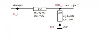
1. acc. attached picture LSE and LSH (another "Right" channel will be similar) are in this places with check points on PCV (right upper side) v. 1.31?
2. If the 1. is OK, then after adjusting BIAS (700k /next time 750K for double check) and after setting in "Parameters menu" LSE/LSH/RSE/RSH minimum resistance (for my project 35...37ohm) I can not start calibration procedure - receive ERROR 10.
3. What is a levels in "Show Statistics" : LSEmin/RSEmin/LSHmin/LSRmin? Because theses levels are not the same as I set in Parameters menu.
I would like to double check :
1. acc. attached picture LSE and LSH (another "Right" channel will be similar) are in this places with check points on PCV (right upper side) v. 1.31?
2. If the 1. is OK, then after adjusting BIAS (700k /next time 750K for double check) and after setting in "Parameters menu" LSE/LSH/RSE/RSH minimum resistance (for my project 35...37ohm) I can not start calibration procedure - receive ERROR 10.
3. What is a levels in "Show Statistics" : LSEmin/RSEmin/LSHmin/LSRmin? Because theses levels are not the same as I set in Parameters menu.
Attachments
What is the error 10 text saying? Forget about show stats, nano can never measure Ldrs correctly, that’s why we still use multimeters.
Try to reset Nano few times without powering off the circuit, see if that will make a difference.
Try to reset Nano few times without powering off the circuit, see if that will make a difference.
You wrote a few pages early : "v1.19 with dual encoder support has a broken calibration"
Does it impact on my ERROR 10 ?
You wrote a few pages early : "v1.19 with dual encoder support has a broken calibration"
Does it impact on my ERROR 10 ?
It’s not relevant, it was causing issues during calibration.
You need to check for hardware and soldering errors. Are all the values correct, components in the correct positions? Error reporting assumes there are no user errors in the assembly process, otherwise all bets are off and errors don’t mean anything.
Last edited:
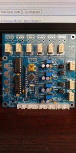
It is assembled acc. your BOM. I double checked. Rechecked soldering too.....
1. Maybe latest v1.31 board request any additional components (as OLED separate powering)
2. What is the differences between NANO soft v. 1.17 / 1.19 / 1.20 ?
1. Maybe latest v1.31 board request any additional components (as OLED separate powering)
2. What is the differences between NANO soft v. 1.17 / 1.19 / 1.20 ?
Attachments
Last edited:
There are no components missing on your board, except C30. You can put 1000uF/10V there just in case.
Can you send a screenshot of the stats page?
Can you send a screenshot of the stats page?
Last edited:
Hi guys!
I have a crazy question.
I'm going to put my RPI (volumio/roon/etc) streamer inside my Purifi based amp + add there this volume module.
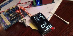
For this reason I would like to see the artist/song and other meta information on a screen.
Can I make my PRI communicating with this module and providing this information on the lcd screen?
Or the opposite? I could attach a colorful screen to my RPI and add there this menu (or dedicated information about volume etc)?
Thanks!
I have a crazy question.
I'm going to put my RPI (volumio/roon/etc) streamer inside my Purifi based amp + add there this volume module.
For this reason I would like to see the artist/song and other meta information on a screen.
Can I make my PRI communicating with this module and providing this information on the lcd screen?
Or the opposite? I could attach a colorful screen to my RPI and add there this menu (or dedicated information about volume etc)?
Thanks!
It's the link in my signature, which seems gone after site upgrade here: https://sites.google.com/view/dacgear/Where can I purchase PCBs for this project?
- Home
- Source & Line
- Analog Line Level
- LDR Pre MkII - LDR volume control and I/O switching