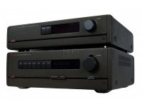
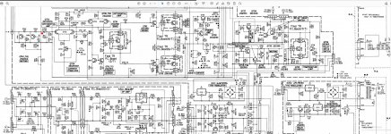
Hi, I have this very old Luxman model A 008 amp that I have never liked how it sounds. Even very basic AV receivers or car amps outperforms it. Currently I run it connected directly to the power section where the red dot on the provided schematic is. Also this cap to the red dot I changed to non polar. The idle current is set according the instructions. What else could I try in order to improve the sound? Thank you in advance
Attachments
Step 1 is make sure your electrolytic caps have low enough ESR. Dried up caps take all the punch out of music that has actual dynamic range, and dried up filter or coupler caps can remove low or high frequencies depending on the design. There are LCR ESR transistor testers running available on amazon & ebay now for $21.wgski recommends longruner. Since I hate Amazon delivery charges for 1 day service I'm going to buy something that looks like it from ebay with 3-5 day delivery.
Step 2. I'm not going to look up all those obsolete part #s, but the driver transistors need to be at least 20 mhz FT and the output transistors need to have at least 2 mhz Ft, to reproduce top octave piano & tinkly bells. I tried TIP31c/32c drivers per many example schematics, and it doesn't work. 6 mhz Ft doesn't cut it. 2n5320/5322 survivors of the big burnup made great sound, Those had 50 mhz Ft. MJE15028/29 instead of TIP31c/32c solved the problem. That was on MJ15003 (NTE60) output transistors.
I already had 20 mhz VAS. Your VAS seems to be distributed, Q706, Q708, Q710. All need to be fast to reproduce 10-20 khz. Don't know why you need such overkill on Ft, but the ear doesn't lie. I have a Steinway console piano to reference the sound of top octave piano of CD & LP tracks. Peter Nero Young & Warm & Wonderful album When I Fall in Love track has top octave Steinway solo piano. Martin Denny Hawaii has a lot of tinkly bells etc to test with.
Don't buy transistors on alibaba, ebay, amazon etc. If you actually get transistors they will be TIP31/32 repainted with a more expensive number. Buy from an ON or ST distributor, newark, digikey, mouser arrow in US. RS & reichelt in Europe.
Last edited:
A said previously if its old then electrolytic caps could be dying.
Either high ESR or starting to go short circuit.
Either high ESR or starting to go short circuit.
Thank you all for the answers! Yes, that was the very first thing I did, to change the big filter capacitors, I just forgot to mentioned it. Nothing changed. The sound is dull and muddy in the midranges. If I have to change individual transistors, it's better to swap the entire amp board with some more modern topology. What kit amp would you suggest? The rail is +-43 volts. Thank you very much
So if you're already considering to replace the whole power amp section, what about readily available chip amp PCB's with one (for 8 Ω) or two TDA7293's (for 4 Ω loads)? A pair of LM3886 PCB's also will fit.
Best regards!
Best regards!
Thank you, I'm a big fan of the minimalistic approach. I really like the "Build this MoFo" project. But it's for single 12-24 volts. Is there any other such simple design that is suitable for +-40 volts? Thank youSo if you're already considering to replace the whole power amp section, what about readily available chip amp PCB's with one (for 8 Ω) or two TDA7293's (for 4 Ω loads)? A pair of LM3886 PCB's also will fit.
Best regards!
Thank you, I just checked all transistor specs. All are in the range 120-130-150 Mhz. Only the output power transistors are 20 Mhz, which is also 10 times more than your recommendation. There is something else wrong, I just don't know in what direction to go. I'm thinking to disconnect the overload protections and the turn on delay. Do you think they could cause such a problem? Thank youStep 1 is make sure your electrolytic caps have low enough ESR. Dried up caps take all the punch out of music that has actual dynamic range, and dried up filter or coupler caps can remove low or high frequencies depending on the design. There are LCR ESR transistor testers running available on amazon & ebay now for $21.wgski recommends longruner. Since I hate Amazon delivery charges for 1 day service I'm going to buy something that looks like it from ebay with 3-5 day delivery.
Step 2. I'm not going to look up all those obsolete part #s, but the driver transistors need to be at least 20 mhz FT and the output transistors need to have at least 2 mhz Ft, to reproduce top octave piano & tinkly bells. I tried TIP31c/32c drivers per many example schematics, and it doesn't work. 6 mhz Ft doesn't cut it. 2n5320/5322 survivors of the big burnup made great sound, Those had 50 mhz Ft. MJE15028/29 instead of TIP31c/32c solved the problem. That was on MJ15003 (NTE60) output transistors.
I already had 20 mhz VAS. Your VAS seems to be distributed, Q706, Q708, Q710. All need to be fast to reproduce 10-20 khz. Don't know why you need such overkill on Ft, but the ear doesn't lie. I have a Steinway console piano to reference the sound of top octave piano of CD & LP tracks. Peter Nero Young & Warm & Wonderful album When I Fall in Love track has top octave Steinway solo piano. Martin Denny Hawaii has a lot of tinkly bells etc to test with.
Don't buy transistors on alibaba, ebay, amazon etc. If you actually get transistors they will be TIP31/32 repainted with a more expensive number. Buy from an ON or ST distributor, newark, digikey, mouser arrow in US. RS & reichelt in Europe.
TDA7293 is max supply +-40. LM3886 is max supply +-42. Luxman is +-43 v. TDA7294 for +-50v is extinct.So if you're already considering to replace the whole power amp section, what about readily available chip amp PCB's with one (for 8 Ω) or two TDA7293's (for 4 Ω loads)? A pair of LM3886 PCB's also will fit.
Rather than buying all these new boards , I buy blown amps & repair them. PV4-c was $40 with freight & took 4 output transistors ($5 ea then, $10 now) and for max wattage, 4 rail caps, $12 ea. 120 w/ch 8 ohms .1% HD. It sounded great amplifying my HDTV before the burglar took it.
QSC CX302 bought this month was $106 plus $70 freight, worked out of the box. 200 w/ch 8 ohms .03% HD. Fan is a bit noisy on the CX302 but can be set behind the LP rack. Full wattage CX302 not tested yet, will probably require $50 of mains & rail caps since it is 25 years old.
Peavey M-2600 is 70 w/ch 8 ohm .1% HD. Cost $110 +freight, worked out of the box. New rail caps were $48 for 4. Listening to it now on SP2(2004) speakers. No fan, no DC speaker protection, which the CX302 has.
Per question post 7, turn on delay & speaker protection don't affect the sound in my Peavey CS800s & QSC CX302. Both .03% HD and pianos & tinkly bells sound like the live ones at Kentucky Center for the Arts.
Last edited:
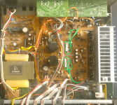
looking at the pcb layout, the output tranies are on a daughter board with leads connected by long plugin leads to the centre of the main pcb, see pic attached. the whole thing looks like a rats nest
If you are, adventurous/curios/bored/a masochist/on a spectrum disorder yet to be defined, you could shorten them and solder to bottom of the pcb to see if there is a difference?
the pics a 007 seems to be the same inside?
If you are, adventurous/curios/bored/a masochist/on a spectrum disorder yet to be defined, you could shorten them and solder to bottom of the pcb to see if there is a difference?
the pics a 007 seems to be the same inside?
Attachments
Thank you all for the replies!
One thing really bothers me on this design. Why there is no cap after D702 to stabilize the rail for the input section? I want to try to put some small cap in the range 10-50 micro farads, but looking at the schematic, I'm not sure if its negative end should be at ground or at minus rail? What do you thing about this? Thank you
To indianajo
Thank you, yes this is a good advice. Broken amps with easy fix problems are often sell for very little money.
To tvi
Thank you, yes, I will see if I could put the output transistors directly on the board. Their place is in the middle of the board and the heatsink montage could be tricky, but I will try this.
Thank you
Generally speaking, Luxman audio gear is high quality.
If your amplfier has always sounded bad, you have to find the cause.
At random replacing electrolytic capacitors, changing the circuit or relocating transistors makes no sense.
If your amplfier has always sounded bad, you have to find the cause.
At random replacing electrolytic capacitors, changing the circuit or relocating transistors makes no sense.
Ok, what approach you suggest? Both channels sound equally bad. But bad not in terms of distorted, just like some low end gear. The power supply is good. Idle current is adjusted. In what direction to search for the problem?Generally speaking, Luxman audio gear is high quality.
If your amplfier has always sounded bad, you have to find the cause.
At random replacing electrolytic capacitors, changing the circuit or relocating transistors makes no sense.
Thank you
You will need to inject pure sine waves at various frequencies, and analyze result at different stages to see where things go bad. Types of analysis could include relative level of different frequencies, and harmonic distortion measurement, or visual appearance on a scope. A PC with line level output and line level input could serve as the test instrument with the right software.
Then where you find the response goes bad, you could analyze problems in that area. I don't see obvious mistakes in the schematic diagram.
Then where you find the response goes bad, you could analyze problems in that area. I don't see obvious mistakes in the schematic diagram.
Thank you, I just think I'm not capable for this yet. I'm still pretty entry level enthusiast. If some day I feel ready for this, will try it. Thank you very much for the answers! Happy Holidays!You will need to inject pure sine waves at various frequencies, and analyze result at different stages to see where things go bad. Types of analysis could include relative level of different frequencies, and harmonic distortion measurement, or visual appearance on a scope. A PC with line level output and line level input could serve as the test instrument with the right software.
Then where you find the response goes bad, you could analyze problems in that area. I don't see obvious mistakes in the schematic diagram.
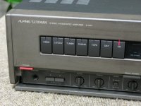
Mine is the next one A-008 and only Luxman is written on the front panel. Not sure if there any big difference with A-007. Thank youIt says Luxman but this is from the period when it was owned by Alpine, not that Alpine is bad, their Alpage Cassette deck are quite nice
Indianajo, it's just vice versa. TDA7293 is ±50 Vdc max, TDA7294 is ±40 Vdc max. Another difference: The 7293 allows the output sections of two or more devices be paralleled. Please have a look at the ST datasheets.TDA7293 is max supply +-40. <snip> Luxman is +-43 v. TDA7294 for +-50v is extinct.
I don't know of any of both being obsolete, but many distributors are out of stock atm.
Best regards!
First I would check the soldering of the printed circuit boards.Ok, what approach you suggest? Both channels sound equally bad. But bad not in terms of distorted, just like some low end gear. The power supply is good. Idle current is adjusted. In what direction to search for the problem?
Thank you
Almost always resoldering some pads is a must.
Second, all switches and potmeters need cleaning with the right type of cleaning sprays.
Third, the speaker relay(s) probably have to be replaced.
Next, find a schematic or service manual and check the power supply voltages of all stages.
I think this is the way to follow for success.
- Home
- Amplifiers
- Solid State
- Vintage Luxman A 008 amp mod