Hi,
After building a few 2-way speakers (which I'm pretty content with) I decided to try to take the leap and try to build a 3-way.
And I'm looking for some feedback on what I believe should be all right.
So after days of trying to find the right drivers that play a little nice together I came up with a system that I believe should work.
My current system will have:
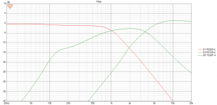
The crossover looks like this:
(Please ignore the shorted / open parts as I was still toying around with values 🙂 )

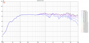
The FRD Like this:

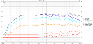
Impedance:

The only thing I'm not sure about is how to interpet phase in VituixCAD and I'm kinda hoping I've done it right 🙂

The drivers itself will be inside a vented enclosure in which I'll make some compartements (the woofer will be in it's own compartement where the mid and tweeter will be stuck together)
So what do you guys think? Is this all right? Or did I miss something / mess something up?
Any feedback will be greatly appericiated!
After building a few 2-way speakers (which I'm pretty content with) I decided to try to take the leap and try to build a 3-way.
And I'm looking for some feedback on what I believe should be all right.
So after days of trying to find the right drivers that play a little nice together I came up with a system that I believe should work.
My current system will have:
- Woofer: Dayton Audio RS225-4 (8")
- Mid: Dayton Audio RS125-4 (4")
- Tweeter: Dayton Audio TD20F-4
The crossover looks like this:
(Please ignore the shorted / open parts as I was still toying around with values 🙂 )
The FRD Like this:
Impedance:
The only thing I'm not sure about is how to interpet phase in VituixCAD and I'm kinda hoping I've done it right 🙂
The drivers itself will be inside a vented enclosure in which I'll make some compartements (the woofer will be in it's own compartement where the mid and tweeter will be stuck together)
So what do you guys think? Is this all right? Or did I miss something / mess something up?
Any feedback will be greatly appericiated!
Attachments
If you've used Dayton's own FRD files to start your modelling, you'll need to add in the effects of bafflestep & edge diffraction, which VituixCAD can do for you (Tools menu > Diffraction), before designing the crossover itself.
If you're expecting to use quite a small mid chamber, that will result in a slightly different impedance curve than the default one, which will likely have been measured in free air. The enclosure module in VituixCAD can model that for you too (Tools > Enclosure). In your case, with quite a high crossover from the low to mid driver, it might not make enough difference to matter, but worth checking to be on the safe side.
Again, if you're using the basic FRD files from Dayton, you'll want to enter in driver offsets to tell the software where they'll be on your baffle - at the moment, they're all in exactly the same place, which would make building it at little tricky... 😉
Generally, we want to avoid having any unnecessary series resistance before a woofer, as all it's doing is wasting power and reducing the overall system sensitivity - so I'd see if it all works fine without that 1st 400mOhm, which it probably will.
Unfortunately I'm still learning about manipulating phase, so I can't really suggest much here - you don't look to be horribly far out, but closer is probably better if you can manage it.
It would be easier to tell your mid & high traces apart if you picked colours that were a bit more different for them though 😉
HTH,
David
Phase gets manipulatdd with frequency, eg. as you fix frequency response (to a direction) the phase gets fixed (to the direction).
But, the phase data, and frequency response, does not reflect reality until one measures the actual speaker. Remember, the xo is not for sake of the manufacturer or for the simulator, but to make your speaker combined acoustic response work in your application!
But, the phase data, and frequency response, does not reflect reality until one measures the actual speaker. Remember, the xo is not for sake of the manufacturer or for the simulator, but to make your speaker combined acoustic response work in your application!
Have a look at the guide in this post it should help with the points above, bear in mind that Dayton's manufacturer responses are not always that reliableAny feedback will be greatly appericiated!
https://www.diyaudio.com/community/threads/vituixcad.307910/post-6841450
There is no z offset included in the simulation to account for the physical offset of the different voice coils, which can only be a guess but without half a guess the phase has no chance of being useful or plausible.
There is a lot of overlap between the drivers, this may have been intentional, but the combined response is above the individual responses for almost the whole speaker, the lack of breakup suppression on the mid is why it is still visible in the combined response.
If you used an 8 ohm mid to help with higher impedance then it would also decrease sensitivity which would help with baffle step on the woofer. Also the tweeter would need to be padded down which would mean a series R on the tweeter which would increase impedance in the tweeter section.
The 720uH on the woofer seems to small (try 3-4mH). You seem to be crossing to the mid above 1kHz. I would aim for about 300 - 350Hz (try 3-4mH) which for a baffle hosting an 8 inch woofer would be approx where the baffle step kicks in.
1- I don't think that tweeter will meet the RS125-4 all that well. The 125's upper limit really is 3kHz, and you have to make it steep/elliptic to even get it there.
2- Agreed on the woofer coil being too small.
3- The aluminum coned drivers need to have the breakup damped to -25dB or more to made benign, with -40dB being much preferred. I don't see any notching to accomplish this, and the RS225's breakup is usually pretty audible without it.
4- ditto on the baffle-effects needing to be factored into the mix, as well as offsets.
I wish you luck, but do your homework.
Wolf
Thank you for your feedback everyone 🙂
I'm aware that there's measuring needing to be done - I've ordered an OmniMic set to be able to do so.
I switched both the woofer and the mid to their 8 Ohm equivalents but I still get drops around 3.2 Ohm, so I'll have to see how that goes when I finished evening out this crossover.
I'm aware that there's measuring needing to be done - I've ordered an OmniMic set to be able to do so.
Your impedance is low also, going below 3 ohms. You would need a good amp to cope.
Yeah, I've noticed the low Impedance as well - I'm planning on building a new amp as well (based on either Hypex or ICEPower) - nevertheless I 'm, attempting to fix the issue.If you used an 8 ohm mid to help with higher impedance then it would also decrease sensitivity which would help with baffle step on the woofer. Also the tweeter would need to be padded down which would mean a series R on the tweeter which would increase impedance in the tweeter section.
I switched both the woofer and the mid to their 8 Ohm equivalents but I still get drops around 3.2 Ohm, so I'll have to see how that goes when I finished evening out this crossover.
Good point! I'm working out a renewed design to cross around that point. I'll maybe replace the Mid as well based on @wolf_teeth 's advice.The 720uH on the woofer seems to small (try 3-4mH). You seem to be crossing to the mid above 1kHz. I would aim for about 300 - 350Hz (try 3-4mH) which for a baffle hosting an 8 inch woofer would be approx where the baffle step kicks in.
Yeah! That was indeed a next step in my list - I'm waiting for the Omnimic to arrive so I can actually measure the drivers on my baffleIf you've used Dayton's own FRD files to start your modelling, you'll need to add in the effects of bafflestep & edge diffraction, which VituixCAD can do for you (Tools menu > Diffraction), before designing the crossover itself.
If you're expecting to use quite a small mid chamber, that will result in a slightly different impedance curve than the default one, which will likely have been measured in free air. The enclosure module in VituixCAD can model that for you too (Tools > Enclosure). In your case, with quite a high crossover from the low to mid driver, it might not make enough difference to matter, but worth checking to be on the safe side.
Again, if you're using the basic FRD files from Dayton, you'll want to enter in driver offsets to tell the software where they'll be on your baffle - at the moment, they're all in exactly the same place, which would make building it at little tricky... 😉
I wasn't aware of no. 3, thank you for pointing that out. I haven't made a build with this particular driver before so I wasn't aware that was a thing.1- I don't think that tweeter will meet the RS125-4 all that well. The 125's upper limit really is 3kHz, and you have to make it steep/elliptic to even get it there.
2- Agreed on the woofer coil being too small.
3- The aluminum coned drivers need to have the breakup damped to -25dB or more to made benign, with -40dB being much preferred. I don't see any notching to accomplish this, and the RS225's breakup is usually pretty audible without it.
4- ditto on the baffle-effects needing to be factored into the mix, as well as offsets.
I wish you luck, but do your homework.
Wolf
Damping or subduing the bell resonance of metal drivers is always something to be aware of.
Wolf
Wolf
To elaborate further on what others have already said.
Woofer and mid should work well together, and considering that after a "normal" baffle step compensation the SPL of the woofer will be around 87-88 dB you need to attenuate the mid (a resistor in series with a woofer is really a no-no). Crossover point can be around 500 Hz or a little lower, a simple correct 2nd order electrical network should provide LR2 slopes on both woofer and mid. This way the breakup on the woofer will be far from the crossover point and maybe naturally damped by the 2nd order filter.
The tweeter is another story, I don't think the one you have in mind will work with the RS125. I'd aim for a crossover point between 2.5 and 3 KHz with LR4 slopes. If you want to stay with Dayton Audio you need to "upgrade" to a ND25FA or a ND28F. There are also better choices with other brands.
You have to simulate baffle step and diffraction and estimate path difference between drivers (important between mid and tweeter), before playing with crossover components.
Zobels are mainly unnecessary, they were sort of required before crossover simulators, so I'd leave them out.
Ralf
Get the woofer level right. your overall sensitivity target is the first thing to set. nearfield and farfield measurement of the RS225 with a good splice. If that is wrong, the rest of the crossover will be too.
- Home
- Loudspeakers
- Multi-Way
- Looking for feedback on a 3-way design