J, welcome and thanks for your post. Many good points.
But I can't really get my head around what you mean by this:
I think the real problem in audio amplifiers is that power supplies inadvertently become active, non-benign parts of the signal path.
Care to amplify?
Jan
But I can't really get my head around what you mean by this:
I think the real problem in audio amplifiers is that power supplies inadvertently become active, non-benign parts of the signal path.
Care to amplify?
Jan
My impression was that it is just dropping charging pulses in order to keep the output at a constant voltage below the nominal output voltage of the transformer. This does not reduce rail noise so much as it makes the rail voltage more of a known quantity so it is easier to design for a given output power. And it does improve rail regulation when the output is playing below 120Hz.
I got a reply which was very long and dancing around the subject.
Tried one more time but I assume he wants to keep his cards close to his chest.
Which I get.
Jan
Tried one more time but I assume he wants to keep his cards close to his chest.
Which I get.
Jan
Our imaginations have already come up with some fantastic stories, perhaps better than his own. Switched capacitor power supplies? Variable reactors?
There are some pictures inside the case here:
https://audiofederation.com/blog/2012/02/28/the-show-2012-at-ces-sanders-speakers-and-amplifiers
If it's what I think it is, then I see it as an improvement on the regulation of a linear PSU with virtually no penalty to power output, and that is a good thing. I can't blame Sanders for writing enthusiatically about a product he designed and wants to sell (if you don't promote your product, you don't get to sell your product, or eat the food you buy with the money it makes). And I can't see any false claims, just withholding of whatever it is he doesn't want to educate his competition with. Maybe he errs in listing no downsides compared to a linear regulator (assuming I'm right about what his circuit is). An error of omission? But do his competitors all list their own shortcomings?
I got a reply which was very long and dancing around the subject.
.... but I assume he wants to keep his cards close to his chest.
Reverse engineering is something that every inventor needs to fear these days and that is in spite of already having taken pains to legally "secure" the hard work. Further, I would expect him to be only extra careful while answering technical questions (even from very qualified people), as many a design has been compromised on an internet forum before.
....I can't see any false claims, just withholding of whatever it is...
In my opinion, anything that has not been published is not meant to be openly available to everyone, as disclosure of too much information about your product usually leads to Chinese replicas. This is especially true if the product is expensive and/or claims exceptional performance.
Had someone in the forum express what appeared to be disgust when I refused to post a schematic and measurements of a circuit (but where I offered to help anyone interested learn how to develop their own version to do with as they please). His complaint before leaving the thread in a huff: "Information wants to be free."...In my opinion, anything that has not been published is not meant to be openly available to everyone, as disclosure of too much information about your product usually leads to Chinese replicas.
I remember reading about this in several places, but this is the only one I can find right now. The relevant text reads:J, welcome and thanks for your post. Many good points.
But I can't really get my head around what you mean by this:
I think the real problem in audio amplifiers is that power supplies inadvertently become active, non-benign parts of the signal path.
Care to amplify?
Jan
"Speaker designers abandoned electrolytic caps back in 1980. But as you can see, they are in almost every transistor output stage, and are required to close the current loop so the final stage can deliver current to the load. The only alternative is quite rare - full regulation for the entire amplifier, not just the inputs and drivers. It's the outputs that need the regulation and isolation from the banks of electrolytics, but this is almost never done. The only transistor amplifier that I know that is fully regulated is the R.E. Designs LNPA-150 - which, by the way, doesn't sound like a transistor amp, but more like a very good triode amp."
As I understand it, current flows from the power supply, through the amplifier output stage, through the speakers, and returns to the power supply - and vice-versa as well. So the power supply is, in a very real sense, part of the signal path - the same electrons flowing through the output devices and speakers also flow through through the reservoir caps, bypass caps, associated semiconductors of whatever type, etc. And there can be more than one of these loops - a class AB or B amplifier that uses a split power supply has at least one current loop in the positive rail and one in the negative. I think the phenomenon is similar to that of poorly laid-out grounds ruining the sound of an amplifier, only more complex and less immediately obvious
A well-designed low-impedance, wide-bandwidth regulator bypasses the reservoir caps and other components similarly to the way a capacitor bypasses a resistor. The importance of good-quality capacitors in the signal path is well recognized. That begs the question "why can't we just parallel lots of quality film capacitors across the reservoir caps, or across the output of an otherwise-inferior regulator?" Unfortunately, I don't have an answer to that - but I'm guessing that somebody else here might. 🙂
The fact that the current loop includes the power supply caps doesn't mean they are in the signal path. In a very real sense, the electrons running through your speaker also run through the pole transformer up your street. Yes, they are not in the signal path.
Look at it as a water supply. The water coming out of your tap comes probably from a watertower miles away. Yet, your tap stream doesn't vary with the level in the tower.
The secret? A system that controls the tap stream. Position of the tap valve.
In audio it's the circuit, generally aided by the feedback control.
Of course, nothing in this world is perfect, and the tap stream does vary a tiny little bit with the tower level, just as the power amp output signal varies a tiny bit with the power supply level & ripple.
How tiny? Its called Power Supply Rejection Ratio (PSRR) and a reasonable value is say 80dB. That means that variation on the supply 'bleed through' to the output at a 1/10,000th fraction.
Jan
I knew as soon as I re-read my post that the "same electrons" thing would come back to bite me. 🙂 And I take your point that the signal doesn't actually flow through the supply. There's still something nagging at me about that though, but i haven't figured out what it is.The fact that the current loop includes the power supply caps doesn't mean they are in the signal path. In a very real sense, the electrons running through your speaker also run through the pole transformer up your street. Yes, they are not in the signal path.
Look at it as a water supply. The water coming out of your tap comes probably from a watertower miles away. Yet, your tap stream doesn't vary with the level in the tower.
The secret? A system that controls the tap stream. Position of the tap valve.
In audio it's the circuit, generally aided by the feedback control.
Of course, nothing in this world is perfect, and the tap stream does vary a tiny little bit with the tower level, just as the power amp output signal varies a tiny bit with the power supply level & ripple.
How tiny? Its called Power Supply Rejection Ratio (PSRR) and a reasonable value is say 80dB. That means that variation on the supply 'bleed through' to the output at a 1/10,000th fraction.
Jan
I remember Walt Jung's regulators and how they were said to allow for much better preamp sound than the 78 series three-terminal regulators. These regulators were for preamps, but the principles are the same. Assuming that they DID sound markedly better, and assuming that simple ripple and diode switching noise were adequately handled by an LM7818 or similar - why did Jung's regulators make preamps sound better? Was it just that even with a good PSRR the artifacts were amplified to audibility in the power amp? Or was the PSRR in those preamps particularly low? I'm struggling to understand why good LC filtering wouldn't work just as well, with the proviso that LC filtering in a solid state power amp is impractical.
I recommend you calculate the values of L and C which are necessary to achieve -70 dB attenuation at 100 Hz, which is the amount of attenuation an LM317 or an LM78xx regulator IC achieves for $1.50. Then try to find a physical inductor and a physical capacitor having those values. How much do they cost? How much do they weigh? How much cabinet volume (in cubic centimeters) do they consume? What is the output impedance of your LC filter at 20 Hertz? Don't forget to include the series resistance of the inductor.
Mark,
You are paying way too much! Even oncies I would pay under half that!
As to inductors, currently a product I need for a power supply design and in thousand piece lots, what I need is above that. Cazapatators however are still quite economical.
Due to the current supply and long lead time issues I am buying what I can for one year’s needs. Getting a bit interesting.
Thanks - I wasn't thinking clearly. I didn't do any calcs - just blue-skied 8.2 mH and 10,000 uF as ballpark values for a preamp drawing about 250mA. At $18 in parts for one rail it's a total non-starter. My bad.I recommend you calculate the values of L and C which are necessary to achieve -70 dB attenuation at 100 Hz, which is the amount of attenuation an LM317 or an LM78xx regulator IC achieves for $1.50. Then try to find a physical inductor and a physical capacitor having those values. How much do they cost? How much do they weigh? How much cabinet volume (in cubic centimeters) do they consume? What is the output impedance of your LC filter at 20 Hertz? Don't forget to include the series resistance of the inductor.
My other question still stands - what combination of characteristics makes a more complicated regulator sound better - if it does - than a three-terminal IC, if the PSRR of the amplifier is very good? I've never done any listening tests on regulators, but enough technically sophisticated people swear by high quality regulation that I think they probably make a difference.
The control bandwidth of a regulator is often compromised for improvements in stability. However, designs that are highly stable (high phase margins) can provide such high PSRR beyond 20kHz, automatically improving error correction throughout the audio range, and can therefore sound better...... I remember Walt Jung's regulators and how they were said to allow for much better preamp sound than the 78 series three-terminal regulators. These regulators were for preamps, but the principles are the same. Assuming that they DID sound markedly better, and assuming that simple ripple and diode switching noise were adequately handled by an LM7818 or similar - why did Jung's regulators make preamps sound better? Was it just that even with a good PSRR the artifacts were amplified to audibility in the power amp? Or was the PSRR in those preamps particularly low? I'm struggling to understand why good LC filtering wouldn't work just as well, with the proviso that LC filtering in a solid state power amp is impractical.
I would guess some way of controlling ground noise would be more effective than a superregulator, as SMPS noise is more likely to show up in the output through ground contamination than through the rails.Thanks - I wasn't thinking clearly. I didn't do any calcs - just blue-skied 8.2 mH and 10,000 uF as ballpark values for a preamp drawing about 250mA. At $18 in parts for one rail it's a total non-starter. My bad.
My other question still stands - what combination of characteristics makes a more complicated regulator sound better - if it does - than a three-terminal IC, if the PSRR of the amplifier is very good? I've never done any listening tests on regulators, but enough technically sophisticated people swear by high quality regulation that I think they probably make a difference.
Thank you - that makes sense. It also suggests to me that even preamplifiers with really high PSRR over the full audio range may still be susceptible to even small amounts of noise on and variation in the supply rails. Does that also apply to power amp output stages? Does a really stiff, quiet supply with a low impedance over a wide frequency range make an audible difference? And is it likely that Mr. Sanders' regulation method supplies that?The control bandwidth of a regulator is often compromised for improvements in stability. However, designs that are highly stable (high phase margins) can provide such high PSRR beyond 20kHz, automatically improving error correction throughout the audio range, and can therefore sound better.
Are there amplifiers with switching power supplies that sound good? I remember them being scorned by audiophiles and I have enough experience with them that I can appreciate the noise problems they cause. Then again, I would expect noise problems to be even worse in Class D amps, but I've heard some that sound pretty good, so maybe SMPS's are sometimes workable even in audiophile gear?I would guess some way of controlling ground noise would be more effective than a superregulator, as SMPS noise is more likely to show up in the output through ground contamination than through the rails.
@jenningthecat, I have a Benchmark AHB2, which uses SMPS. It measures great in terms of distortion and noise (as they are typically measured). However, I believe it may suffer from some degree of signal-correlated noise modulation. Its a potential problem Bob Cordell briefly touches on in one of the later chapters of the 2nd edition of his book, although IIRC he doesn't go into detail about how to measure it. Pity.
More than 100 diyAudio members absolutely LOVE the VFET power amp kit, designed by Nelson Pass and sold by diyAudio. It used the SMPS shown below. I write in the past tense because all amplifiers were pre-sold via a lottery and there are no more, there will be no more, all are gone forever.
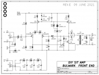
Also attached is the schematic of one of the four alternate "front end" cards, to get a feel for their functionality.
_
Also attached is the schematic of one of the four alternate "front end" cards, to get a feel for their functionality.
_
Attachments
You can design a quiet SMPS yourself if you understand the technology, but if you are an audio company the cost inflates dramatically to find someone who will do the same thing for money, with knowledge of international electrical codes (okay, this is probably just my own stupid guess). So it is common to just go with a linear PSU or use an off the shelf SMPS and live with the noise. A low-noise SMPS is a special beast as far as marketing is concerned and probably costs much more than a linear PSU. And there is the stigma to overcome.
A ZSRP is just a ground plane which isn't used to supply current to anything (hence Zero Signal Reference Plane). So it plays no role in the design except to counter magnetic fields or for E-shielding. If a current loop is placed over a ZSRP, an opposing current loop will form in the plane which cancels the field of the first current loop. Since the only currents in a ZSRP are magnetically induced, they follow the signal current paths for the most part and the plane is inactive for frequencies where the skin depth is larger than it's thickness. I am interested if anyone has an example where currents in a ZSRP follow an unwanted path.
A ZSRP is just a ground plane which isn't used to supply current to anything (hence Zero Signal Reference Plane). So it plays no role in the design except to counter magnetic fields or for E-shielding. If a current loop is placed over a ZSRP, an opposing current loop will form in the plane which cancels the field of the first current loop. Since the only currents in a ZSRP are magnetically induced, they follow the signal current paths for the most part and the plane is inactive for frequencies where the skin depth is larger than it's thickness. I am interested if anyone has an example where currents in a ZSRP follow an unwanted path.
Last edited:
PSRR is equally applicable to all kinds of amplifiers. However, actual rejection at the output depends on gain, as PSRR is usually RTI.Does that also apply to power amp output stages? Does a really stiff, quiet supply with a low impedance over a wide frequency range make an audible difference? And is it likely that Mr. Sanders' regulation method supplies that?
That is, Output rubbish = Gain x Supply rubbish / PSRR.
In Mr. Sanders' method, the low impedance of the supply for >120Hz is largely going to be due to the huge capacitor bank, and not active regulation. However, I think this is still better than an unregulated power supply running the same amplifier.
- Home
- Amplifiers
- Power Supplies
- Ideal, no-loss linear regulator?