I think it's plausible that all amplifiers sound the same. I also think it's plausible that they don't. When I think about it, it makes my head hurt. The question isn't easy. I will claim that anyone who says it's straightforward immediate disqualifies him or herself from serious consideration of their viewpoint.
.
(Not specific to ASR or anyone else)
One thing that gets me is the tendency to treat 'components' as separate units that don't interact. Measuring an amplifier with an ideal 8ohm load is nothing more than a scientific curiosity that ignores reality.
People forget that speakers are full duplex at all times, so when you apply a signal, the reverberations from the cone in particular but also from the box and air cavity will create delayed reflections that produce voltages and currents.
These delays mean that the phase is unpredictable, and if the amplifier uses negative feedback to linearise itself, the addition of a speaker may sabotage its 'own' performance (not that it's relevant how well the amp performs all by itself, when the whole point is for speakers to sound good at the end of it all).
Off hand I'd say that high sensitivity speakers would be more demanding and revealing of an amplifier's shortcomings here, because the microphone effect is much stronger. Not to mention that the signal gets a little more distorted each time it gets converted into a different form.
I've noticed a few oddities.
Cone break-up is often taken as a bane and a huge limitation, allegedly because of those variations in sensitivity. Yet others find full-range speakers not only usable but worthy of better amps. Interesting...
Similar deal with horn speakers.
For some reason I thought the thread was in the 'lounge' section. Not sure headphones would have all of the same issues as room speakers. The air cavity between the speaker cone and the ear would behave a bit differently, I think.
There is a lot of variation between different headphone designs. Impedances differ, as do power requirements. Means an HPA should be tested with a variety of headphones to make sure performance doesn't vary. That's one of the reasons Stereophile says they use Pass HPA-1 as a main reference HPA: because its sound doesn't change with different headphone loads. Any differences in sound may then be attributed to the headphones under review.
A one-size-fits-all might offer the best convenience, but does it offer the best possible performance?
For 32 ohms, 1mW is achieved @ 0.179V and 5.6mA.
A 600 ohm set would require 0.77V and 1.3mA.
To support 32 ohm you need a much higher max current, which has its compromises. Similarly, to support 600 ohms the voltage has to be higher, which comes with a different set of compromises. To do both, they start compounding.
For some reason I thought the thread was in the 'lounge' section.
Yeah, LOL. Having done some mildly interesting design/build work, I feel pressure to keep delivering the goods. But I've hit a wall because there's nothing in the EE curriculum, given my limited understanding, that tells me where to go next.
I read all thirty-six pages of the HPA-1 clone thread last night. This preamplifier, which is the darling of subjective reviews everywhere, tantalizes us with the prospect that a different method can take us well beyond the run-of-the-mill and reveal a higher level of performance that defies simplistic characterization. This is why I'm stuck right now with my head in my navel. Yesterday, I read a short book of philosophy by C. S. Lewis. You may thank me for not going on about it, and why I think it's relevant to audio.
On a slightly more mundane topic, I often read comments about how the loudspeaker drives current back into the amplifier output terminals, interacting with the feedback loop and introducing distortion. This is sometimes offered as a justification for zero-feedback designs. I'm not saying your observation is wrong. But I think some people misunderstand this "Back EMF" concept. The loudspeaker is an electromechanical system with energy storage elements and inherent time delays. This is nothing mysterious, and can be represented to a close approximation by the equivalent passive RLC networks, with the associated frequency-dependent electrical impedance and phase. In that sense, what you are saying is that amplifiers ought to be designed to work well into reactive loads. This is good advice, but easy to overlook. Reading the 6Moons review of the HPA-1, one of the explicit design goals for the HPA-1 was that it should perform well driving all manner of headphones, as Mark points out.
Well I spent a couple of years chasing Blameless topology power amplifiers amplifiers and eventually achieved measured 0.001% THD and very low noise. However I don't like how it sounds compared with a simple and low cost Krell KSA-50 clone. I can not tell you why, however. I am in the middle of a similar journey on headphone amplifiers and after various well spec'ed designs (including TPA6120A2) I am building the HPA-1 to see if I have a similar experience with that as I had with Blameless versus the KSA-50 clone.
I'm encouraged by the number of people who seem to be having good luck with the DIY HPA-1. I think I might give it a try.
On a slightly more mundane topic, I often read comments about how the loudspeaker drives current back into the amplifier output terminals, interacting with the feedback loop and introducing distortion. This is sometimes offered as a justification for zero-feedback designs. I'm not saying your observation is wrong. But I think some people misunderstand this "Back EMF" concept. The loudspeaker is an electromechanical system with energy storage elements and inherent time delays. This is nothing mysterious, and can be represented to a close approximation by the equivalent passive RLC networks, with the associated frequency-dependent electrical impedance and phase. In that sense, what you are saying is that amplifiers ought to be designed to work well into reactive loads. This is good advice, but easy to overlook. Reading the 6Moons review of the HPA-1, one of the explicit design goals for the HPA-1 was that it should perform well driving all manner of headphones, as Mark points out.
After hearing some anecdotes and looking into them I discovered Esa Meriläinen and current-drive.info where he argued about various distortion benefits of current drive vs voltage drive, which convinced me enough to try it out for myself.
(Waiting on parts.)
The usual bass resonance is easy enough to model and even be tuned manually. Break-up modes could probably also be added individually, but there's so much going on:
Coil overhang and geometry wrt the magnetic gap, so there are variable voltages across different parts of the coil. Merilainen argues that the force applied is proportional to current not voltage, so the back-emf with voltage drive is mostly just wishful thinking.
Coil displacement creates secondary distortion like IMD.
I read elsewhere that the permanent magnets have a memory effect as well. With complex signals you get glitches in the hysteresis that manifest as noise because their timing depends on unknown future signals that activate them.
As for feedback. It's a wondrous idea, but I'm careful about weighting. With the ear being most sensitive in the 1-4kHz baby-scream range,..
If you add NFB, a 100Hz test signal with a small 200Hz error gets fed back, eliminating most of the error but also creating IMD because the amplifier has both 100Hz and 200Hz at the input, creating a new 300Hz error and so on in a never-ending loop. Strong NFB to reduce THD will tend to raise those higher harmonics until they are subjectively much louder than the low harmonics because of the Fletcher Munsen curve, and masking effects are more lenient on low harmonics.
Now imagine a complex signal with a speaker attached. The speaker has its own IMD and reverb that gets distorted again (electrical -> mechanical -> electrical) so in terms of 'errors' it's indecipherable garbage that feedback can't fix anyway.*
Actually maybe that's not entirely true, but I think there's a price: reduced total error amplitude -> increased error complexity.
Last edited:
This is straying from the subject at hand, but it doesn't really bother me.
I haven't really studied current drive, so I'll trust what you say. Current in the voice coil is what drives the speaker, so it all boils down to the exact same thing in the end, and it's just a question of how you get there, seems to me.
The distortion-multiplying effects of negative feedback are well known. The equally well-known answer is it's claimed to be better to have a raft of vanishingly-low higher-order distortion products no one can hear than plainly audible low-order ones. But people disagree with that, too. I don't buy into the notion of consonant even-order harmonic distortion because that always produces obnoxious IMD. Also common knowledge.
It seems to me the modern "distortionless" amplifier is a legitimate baseline, and you can get damned good sound with this kind of equipment. From there, you may or may not believe you can improve it, and it boils down to personal taste, digging deeper into circuit optimization, possibly-real-but-unappreciated nonlinearities, and straight-up self deception.
For every seemingly convincing claim you can find someone else who convincingly refutes it. John Curl is widely regarded as a design genius, but he fricking believes in ByBees, for heaven's sake. I learned in my college predicate logic class that a single logical contradiction invalidates an entire proof. I dunno what to say. Sometimes I think it's all too much to think about.
I've built three headphone designs this year, and each seemed like a revelation to me compared to what I had before. At other times, the differences seemed insignificant. This is a very peculiar hobby, with so much navel-gazing. Could be time to take a break.
...John Curl is widely regarded as a design genius, but he fricking believes in ByBees, for heaven's sake.
I know John as a personal friend. He is a serious guy. There is more to the Bybee story than you probably know about, so it is suggested not to jump to conclusions. More tomorrow, if things are still unsettled.
I knew that would be a controversial comment, and I realized John is your friend. Sorry. 🙂
I don't buy it, but welcome solid proof of the working principle of the ByBee. I haven't looked at the arguments in a long time, but my recollection is that I wasn't convinced. Maybe that's the point, which is that we're trying to forge agreement over something that's inherently disagreeable. LOL, that was a joke. I mean, maybe it's like coming to blows over the question of whether beef or lamb is tastier.
Edit: Or maybe the point is, to be human is to want to punch your neighbor because he prefers his steaks well-done, and you prefer medium rare.
Critics should wait till that secret listening test results come out, right?I know John as a personal friend. He is a serious guy. There is more to the Bybee story than you probably know about, so it is suggested not to jump to conclusions. More tomorrow, if things are still unsettled.
More like business colleague.I knew that would be a controversial comment, and I realized John is your friend. Sorry. 🙂
John's support (without evidence) for ByBee is a business / political decision.I don't buy it, but welcome solid proof of the working principle of the ByBee.
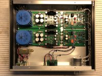
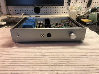
I've decided, on Mark's recommendation, to build an HPA-1 clone. If I had realized how many amplifiers there are called HPA1 or HPA-1, I'd have named my own projects differently. This is going to be a nuisance.
Anyway, I'm going to go away for a while, but I'll be back when I have something to share. Of course, I'm happy to respond to any comments or questions about my own HPA1/2 designs. I know a few people are working on projects based on what I posted here. I'm looking forward to news on that front.
Anyway, I'm going to go away for a while, but I'll be back when I have something to share. Of course, I'm happy to respond to any comments or questions about my own HPA1/2 designs. I know a few people are working on projects based on what I posted here. I'm looking forward to news on that front.
I think I mentioned earlier I broke the stop on my Elma attenuator. Two weeks ago I ordered an Eizz attenuator from China. It arrived today and I installed it.
TBH, I don't like it. My immediate reaction was that it lost some detail. The Eizz uses carbon film resistors. It sounds exactly like what you read: not bad, a little warm and smooth. Everything is still there, but it's lost some sparkle.
The damned thing is I can't hear a difference, short-term, when I swap back and forth with the Topping. But the subjective impression remains.
I may take the thing apart and replace the resistors with metal films. I'm not sure it's worth the bother. It's possible I'm just fooling myself. Maddening hobby, this.
Attachments
The loop gain will show some peaking at the lower corner frequency. Playing in SPICE, you can get an idea of the effect of varying the values of each component. You can get rid of the peak by implementing three-pole compensation. You do this by adding a third capacitor in series with the resistor. 150nF is a good starting point. Then you spend some time iterating in SPICE and hope your models are accurate. I haven't tried three-pole compensation yet, but plan to in my next design.
Apologies for digging up this old post of yours, but I'd like to point out that I think you may have missed the final "bonus" page of my paper. In the original published version, I did indeed refer to this configuration as "three pole", but alas that was erroneous. The response is still two-pole (and a zero), but you now have control over the Q of the poles. My preferred name for this compensation is "split two-pole" compensation, because you can split the complex poles into two distinct real ones. This is explained in more detail on the final "bonus" page of the paper.
As I said earlier, a very small capacitor (1-2 pF) across the whole network completely alters the response.
This will also give an overall two-pole response with split poles. However, as you note, it is extremely sensitive to the value of the bridging capacitor.
On another note: I didn't have time to read the thread thoroughly but did notice some discussion of output transistors. Apologies if you already mentioned it, but did you look at the 2SC6144SG & 2SA2222SG pair? They are very fast and have excellent current-gain linearity.
Apologies for digging up this old post of yours, but I'd like to point out that I think you may have missed the final "bonus" page of my paper. In the original published version, I did indeed refer to this configuration as "three pole", but alas that was erroneous. The response is still two-pole (and a zero), but you now have control over the Q of the poles. My preferred name for this compensation is "split two-pole" compensation, because you can split the complex poles into two distinct real ones. This is explained in more detail on the final "bonus" page of the paper.
This will also give an overall two-pole response with split poles. However, as you note, it is extremely sensitive to the value of the bridging capacitor.
Thank you for the clarification. I was wondering why you called it three-pole compensation, and this explains it.
I've noticed, IIRC, that you can knock down the peak, and even get the poles to split, if you use a really low value for the resistor in the conventional TPC network. That doesn't seem ideal. Your series capacitor seems like the best solution and I plan to use it in future projects.
Your paper really helped me make sense of TPC, thanks.
I haven't looked at those transistors. I'll check them out.
Last edited:
Your paper really helped me make sense of TPC, thanks.
No problem. I'm pleased that it's been useful 🙂
A third option for controlling the peaking is to bridge the network with a high-value resistor.
One thing I never had a chance to investigate was clipping behaviour of the suggested arrangement. It's possible that a high-value resistor in parallel with the additional capacitor may be a good idea.
I imagine that my proposed arrangement from the paper, a bridging capacitor, and a bridging resistor will all have unique clipping behaviours.
I haven't looked at those transistors. I'll check them out.
Mouser currently have the 2SA part in stock with the 2SC part due on 24th Dec. Digikey have plenty of both.
Mouser currently have the 2SA part in stock with the 2SC part due on 24th Dec. Digikey have plenty of both.
There's also the 2SA2040/2SC5707. They're even faster with about half the Cob, but they have a much lower early voltage.
One thing I never had a chance to investigate was clipping behaviour of the suggested arrangement. It's possible that a high-value resistor in parallel with the additional capacitor may be a good idea.
I imagine that my proposed arrangement from the paper, a bridging capacitor, and a bridging resistor will all have unique clipping behaviours.
Mouser currently have the 2SA part in stock with the 2SC part due on 24th Dec. Digikey have plenty of both.
I started out using D44/45H11 in my Blameless-style amp, then switched to KSA1220/KSC2690 for the next one. I've been collecting through-hole transistors I will probably never use, just so I don't regret it later if I need them. I'll look up the ones you suggested and pick up a few the next time I order parts. Thanks for the suggestions.
I had really nasty problems with clipping instability in my first amp design. The second one, based on a Bob Cordell power amp circuit, makes extensive use of diode clamps and the VAS is inherently current-limited. It's never shown the slightest hint of misbehaving.
I'm a minor-league player here, haven't really dug too deep into all this. If you ever do a follow-on paper, I'd love to see an analysis of the impedances looking into both ends of the compensation network across the frequency spectrum, and how this impacts overall performance (including loading of the IPS and VAS and stability issues when things saturate/clip). The derivation for the TPC network makes the assumption that the input to the VAS is a virtual ground, and it seems like that's not true at lower frequencies where there isn't much feedback around the VAS.
- Home
- Amplifiers
- Headphone Systems
- New Headphone Amplifier Design