The catch is they actually did connect the diodes in the circuit the correct way (if it works).
Maybe somebody else made the schematic, and the guy didn't look at it too closely.
Maybe somebody else made the schematic, and the guy didn't look at it too closely.
Because they get many thousands likes, million views, exaggerated praise, etc.I thought so.
Why do they have it on their web page and youtube videos?
Thanks.
You are scratching the bottom of the barrel as far as Electronics videos go, and that compared to a very poor average.
DIY Powerful Ultra Bass Amplifier Z44N MosFet, No IC, Simple circuit - YouTube

HOA KỲ
DIY Powerful Ultra Bass Amplifier Z44N MosFet, No IC, Simple circuit
1,450,374 views 😱
Mar 18, 2021
20K
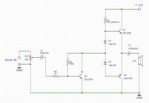
Even with the diodes in the right direction the low-sideoutput pnp will never see any base current.Can anyone explain why the direction of d1 and d2 diodes is opposite in these simple circuits? Thanks.
No stabilisation of output bias voltage at all.
The hole schematics is a pile of crap😛
JMFahey, I like it!
Fully understand that these people are trying to have as many hits on yt to earn some money.
Still, the link to webpage i posted looks like more serious stuff.
Fully understand that these people are trying to have as many hits on yt to earn some money.
Still, the link to webpage i posted looks like more serious stuff.
JMFahey, I like it!
Fully understand that these people are trying to have as many hits on yt to earn some money.
Still, the link to webpage i posted looks like more serious stuff.
The link you posted actually comes up with a fraud warning when trying to enter 🙂
Attachments

Last edited:

Can anyone explain why the direction of d1 and d2 diodes is opposite in these simple circuits? Thanks.
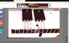
If we look at the site Pictured Version then we also see that the Emitter of 2SC2383 is connected to Collector of 2SC1943, so this give already another circuit..
Also read the Text.. Blue highlighted in the screenshot
Also in this picture below we can see the diodes are connected the correct way, mistake or bummer one or the other..
One of the both isn't accurate or possible both..
The Circuit will run when diodes are connected the visa versa./.
Have run it in my Simulation program.
Attachments

Last edited:
It's just an expired security certificate! Browser tells me that Security Certificate has expired on day ago..At first i had no issue accessing the page, now it gives me warning too. You can access it on your own risk. Or run your browser in secure mode.
if you have a good firewall and Anti Spy - Spam then nothing to worry about..
Thanks hpro for checking it out.
I have lots of c5200 and a1943, i will build it just for fun of it.
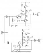
But not the first schematics, second one in first post, the one showing feedback. That looks better and should eliminate some nasty crossover distortion.
Ultimately, i will build classA jungson with these outputs, i am just waiting for heatsink.
So was looking around for fun.
Cheers!
I have lots of c5200 and a1943, i will build it just for fun of it.
But not the first schematics, second one in first post, the one showing feedback. That looks better and should eliminate some nasty crossover distortion.
Ultimately, i will build classA jungson with these outputs, i am just waiting for heatsink.
So was looking around for fun.
Cheers!
Is direction of D3 correct or not? ;-)
Yes, D3 is at the base of PNP transistor TR4.
- Home
- Amplifiers
- Solid State
- Direction of diodes in an amplifier