Hello,
i'm doing a metal preamp that uses 12 vdc for heaters. So i used the 12V winding for the heaters with a diode bridge (4x1N4007). It works good.
But i used the 6.3V winding to give 6 vdc to the relays and the leds. I used a bridge that is 80 v 1.5 A and a 6 v voltage regulator (with 2 capacitors) and the bridge burnt after 2 secondes of no load at all, the relays were not connected.
Why?
Thanks
Pictures and schematic? Sounds like you reversed something.
BTW, There's a PCB for that 🙂
I needed to drive a relay like you but I use 12V ones.
The Little Delon
BTW, There's a PCB for that 🙂
I needed to drive a relay like you but I use 12V ones.
The Little Delon
Last edited:
Thank you for your reply. I did not see any mistake except that the solder joints are very close to each other (2.4 mm strip board), but the bridge has shorted. Maybe a bad part, or electric arc (with 6.3 v ?), i don't know.
Thank you for the voltage doubler schematic, i hope i can use it...
Thank you for the voltage doubler schematic, i hope i can use it...
With a bridge rectifier you will not get much more than about 7 Vdc from a 6.3 V ac winding (and often even less than that). This is mainly caused by the voltage drops over the diodes in the bridge rectifier (two of the four diodes are passing current at any time). The voltage regulator needs a minimum amount of voltage over it to function properly (this voltage can be found in the datasheet; often it's something like at least 3 V). So 6.3 Vac is just not high enough to achieve what you want. I estimate that you would need something like 9 Vac to make it work properly (but to be shure the exact type of regulator should be known).
Addition: Or use the voltage doubler like kodabmx showed (but doubling the voltage will leave you half the current so be sure this all fits with the transformer and the relays).
I can't link the bridge rectifer burning up without the voltage regulator being loaded. Maybe I could if more details about the circuit and parts would be available.
Last edited:
2.4mm shouldn't be any issue for 6V. 300V doesn't arc that distance in most cases.
If the bridge failed short, it's output was somehow shorted. Or it was connected wrong. Unless you draw substantial current through the diodes, they won't blow up.
If the bridge failed short, it's output was somehow shorted. Or it was connected wrong. Unless you draw substantial current through the diodes, they won't blow up.
I started over my little board, and i get 6.0 V after the regulator and no smoke.
So i don't know what happened previously...
Thanks for the support
So i don't know what happened previously...
Thanks for the support
Hi I know formulas and exact knowledge are something of the past (or is it the future?) but it would be better to use a regulator that works also in worst case conditions. This means either a larger filter cap and/or a low drop regulator.
6.3V x 1.41 = 8.883V. Now ripple voltage and diode forward voltage need to be distracted. This is about 1V ripple with a 2200 µF cap (at 1A) and around 1V for the diode x2! This leaves little room for a 7806 to work OK. It works with a dropout voltage of 2 ...3V. Stuff should also work OK when the mains voltage is lower than 230V.
In the calculated way of doing stuff we work with loads in Amperes and caps in microFarads (µF). If you know the load you can adjust the capacitance of the filter cap. Rule of thumb is 2200 µF per 1A for 1V ripple voltage. Since the situation seems tight a lower ripple voltage seems advisable.
I would definitely use a 4700 µF cap for even just 1A and Schottky diodes like 11DQ10 (for lower Uf) when the load is not higher than 1A and an LDO.
Last edited:
Was the regulator loaded when you measured 6 Vdc?
I don't understand how a 7806 could work in this situation since it needs an input voltage of at least 2 V higher than the output voltage, so it would need atleast 8 Vdc at its input. Looking at the datasheet of the bridge rectifier, it will drop at least 0.6 V per diode (is says 'per element' which I understand as 'per diode'), so at least 1.2 V in total. That would mean the output voltage of the bridge rectifier would at best be (6.3 - 1.2) x 1.41 = 7.2 Vdc.
Maybe your tranformer gives of more than 6.3 Vac?
It should always be measured and tested under load. BTW even though a normal diode has 0.6V forward voltage calculation is done with 1V. Worst case as in maximum allowable current. This is 1.1V @1A for the popular 1N400x series. 0.85V @1A for 11DQ10.
@PFL200: you forget to distract ripple voltage.
@PFL200: you forget to distract ripple voltage.
@ jean-paul. Could you please help me a bit more on this? Or a link to an explanation? What should I have distracted from what?
I think it was a typo, probably "subtract".@ jean-paul. Could you please help me a bit more on this? Or a link to an explanation? What should I have distracted from what?
Thanks. I understood it as 'substract' eventhough I also wrote it wrong. So my question for help remains the same. What should I have substracted from what?
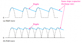
Yeah typo, heavy case of the flue right now. You should subtract the ripple voltage. The filter cap is meant to make the pulsating DC a flat line but alas nothing is perfect and there is a load so a ripple voltage is the result. "Rimpelspanning" in dutch.
If the ripple voltage is high (with a too small cap for instance) chances are likely that the regulator also malfunctions due to too low input voltage. This is when the lower level of the ripple voltage is lower than the minimum input voltage of 7806. This occurs when the transformer voltage is close to the desired regulated DC output voltage. We do this to reduce energy loss (in useless heat) so it is a good thing to spend some time on calculation. Reducing useless heat is good but a PSU that malfunctions when mains voltage is 220V is not.
When using a Graetz bridge: (Uav x 1.4141) - Uripple - 2x Ufdiode
Last edited:
OK, thanks. I think I understand. So in practice things are even a bit 'worse' than I calculated.
Yes they are. In this case a very large filter cap and Schottky diodes are mandatory. When one works with LDOs quite often it becomes obvious when using let's say a 6V transformer for 5V DC output regulated. It is possible but with some tricks. It is better than using a 9V transformer for 5V output 🙂 Things then depend strongly on the used transformer and the load. Many transformers have higher output and loads can be a meagre 600 mA....
Attachments
Last edited:
My DMM says :
(with no load) : winding : 7.2 VAC
before regulatior (after bridge) 8.3 VDC
After regulator : 6.0 VDC
I think the winding gives 6.3 VAC with a heavy load ( several tube heaters)
BUT if i feed one relay, it drops to 5.37 VDC
(with no load) : winding : 7.2 VAC
before regulatior (after bridge) 8.3 VDC
After regulator : 6.0 VDC
I think the winding gives 6.3 VAC with a heavy load ( several tube heaters)
BUT if i feed one relay, it drops to 5.37 VDC
You forget to measure input voltage of the regulator under load. You also forget to mention how much current the load draws. And you forget to mention the value of the filter cap. That are 3 too many forgotten factors that determine success/failure 😀
- Home
- Amplifiers
- Tubes / Valves
- Using 6.3 v winding for relays power supply