You still give insufficient information.
1. What is the current the relays draw? You can give the type number and I will look it up
2. What is the value of the filter cap?
7.01 V DC is too low for a 7806. It needs its input voltage to be at least 2V above output voltage so 8V.
1. What is the current the relays draw? You can give the type number and I will look it up
2. What is the value of the filter cap?
7.01 V DC is too low for a 7806. It needs its input voltage to be at least 2V above output voltage so 8V.
Last edited:
relay : Tube-Town Store - Finder Relays DPDT , 125V 2A, 6V
Filter caps : i put 2 x 100 µF one at the input, one at the output 😕
Filter caps : i put 2 x 100 µF one at the input, one at the output 😕
That relay uses 33 mA a piece so 100 mA in total for 3 of them in parallel. We round it to 150 mA worst case. That is a very light load. But... your filter cap is way too small even for this light load. Please use a 2200 µF 16V cap before the regulator. I think you can get away with it when having such a light load. The output capacitor is OK with 100 µF.
BTW you can buy bog standard electronic parts at distributors. No need to fill the pockets of tube orientated stores.
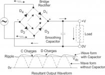
Have a look at what that filter capacitor does or should do and try to imagine what happens when the cap is chosen too small. It helps to see worst case i.e. "wave form without capacitor":
BTW you can buy bog standard electronic parts at distributors. No need to fill the pockets of tube orientated stores.
Have a look at what that filter capacitor does or should do and try to imagine what happens when the cap is chosen too small. It helps to see worst case i.e. "wave form without capacitor":
Attachments
Last edited:

Hi, your way of dealing with this stuff is incoherent. So the load is 150 mA for 3 relays and 4 LEDS of each 20 mA. I don't believe this as normal modern green/red/amber LEDs need 2.5 mA to glow otherwise one goes blind when looking at them. That makes a maximum of 160 mA and this will be lower in real life. You don't need to double anything except that you need a large filter cap to minimize ripple voltage either with 6V or with the voltage doubler (which makes its necessity exactly 0).
Just buy that 2200 µF cap and be done with it. It will work OK. Also use the 1N5817 Schottky diodes. If you only have 470 µF well then use a few in parallel. You need to get ripple voltage down in any case.
NICHICON KW Condensateur electrolytique 2200uF 16V - Audiophonics
You really have all the necessary stuff except a 1.60 Euro electrolytic cap...... The voltage doubler also needs larger caps than you have and then the reg needs to dissipate power to useless heat without any reason. You will then still use 7806 as you have 6V relays....A 7806 dissipating 1W then while feeding a few LEDs and relays.
Last edited:
For the twin caps, I usually use 1000uF. The third cap isn't necessary for the relays and can be omitted (like the picture of the "Little Delon, vs the picture in the first post of that same thread).
The 7812 can be replaced with 7806 for 6V output (obviously).
I run 10mA through an ordinary small red LED indicator, but I only run 0.3mA for the blue ones. You could still land a plane with them.
The 7812 can be replaced with 7806 for 6V output (obviously).
I run 10mA through an ordinary small red LED indicator, but I only run 0.3mA for the blue ones. You could still land a plane with them.
Last edited:
The OP needed some help to get a proper 6Vdc supply for his relays and LED. So far the discussion was about why he can’t reliable get 6Vdc regulated supply from 6.3Vac.
But why is a regulated supply needed to drive a relay? I probably would simply rectify the 6.3Vac and size a resistor of proper wattage to get 6Vdc for the relays
But why is a regulated supply needed to drive a relay? I probably would simply rectify the 6.3Vac and size a resistor of proper wattage to get 6Vdc for the relays
Let him first start to understand the basics. Regulated or unregulated.... 100 µF is a tad too small in either case. An 7806 is cheaper than a proper wattage resistor and it is more elegant.
Last edited:
OK, i'm just a little impatient to see it working, and want to do with what i have in sotck.
I have only 2 6v relays and many 12v relays. But in any case i have to order some parts. I just wanted to spare a week of transit....
I'm like this, sorry, but you are right...
I have only 2 6v relays and many 12v relays. But in any case i have to order some parts. I just wanted to spare a week of transit....
I'm like this, sorry, but you are right...
And if you're interested in a small board with the parts you need, PM me.
3$ each, 15$ for air postage.
3$ each, 15$ for air postage.
OK, I'm just a little impatient to see it working, and want to do with what I have in stock.
I have only 2 6V relays and many 12V relays. But in any case I have to order some parts. I just wanted to spare a week of transit....
I'm like this, sorry, but you are right...
I know. It is cheapest and most elegant. It takes only 1 part. The voltages are right too. Please use the 1N5817 (you don't reply on suggestions).
Final question: you do know the current rating of the 6.3V winding I hope? It should be at least 500 mA.
Last edited:
Your relay has a wide coil operating range - something like 4.5 -9 Vdc to operate the coils. So, perhaps there is no problem 😀
I tried the voltage doubler with 2x100µF twin caps, 470 µF at input and output of a 12V regulator. I get 11.77 v output with or without the 3 relays engaged.
But i did not try my preamp yet.
I'll redo the board with better capacitor....
Thanks a lot guys!!!!
Edit : not at all, i get 10 v with 3 relays engaged...
But i did not try my preamp yet.
I'll redo the board with better capacitor....
Thanks a lot guys!!!!
Edit : not at all, i get 10 v with 3 relays engaged...
Last edited:
Everything is working so far with 10V on the 12V relays and a 12V regulator?!? I am glad I can't follow the logic. What you created with the fully redundant doubler is a higher voltage with still too much ripple voltage as the caps are still too small 😉 Instead of being closer to a solution you are further away from it as the regulator does not regulate anymore.
Is it so hard to understand simple electronics? After rectifying a pulsating DC voltage is available that must be smoothened with a filter cap. The filter cap value determines the ripple voltage. Or is this the in this section famous "just doing something" doctrine?
Is it so hard to understand simple electronics? After rectifying a pulsating DC voltage is available that must be smoothened with a filter cap. The filter cap value determines the ripple voltage. Or is this the in this section famous "just doing something" doctrine?
Last edited:
- Home
- Amplifiers
- Tubes / Valves
- Using 6.3 v winding for relays power supply