No, these 8 big caps won't lead to oscillations. I have them on my dac now and I have my circuit tested. No oscillation even without any 2r2 resistors between my power supplies and the dac.
Asilker,
My recommendation would be to build the dac board as Miro’s laid out originally. Listen in that form and get a reference. Nice suggestions by Hidy but they are specifically tuned for the power supplies he’s using and his ears.
Just warning you now, this project really doesn’t have an ending 😀
There will be plenty of time for tweaking PSU’s, playing with I/V and output stages.
Vunce, I will take your advice. Building it up stock first is my plan. 🙂 BTW you weren't kidding about part shortages when we talked last week.
Hidy - The 100uf / 100nf arrangement that's on the 12v rails of the AD1862 on the DAC board are identical to the cap arrangements on the PSU2 board. As per the PSU2 updated schem and jl sounds v1.3 shem:


Apparently this 100uf / 100nf arrangement is pretty much standard for regulator designs (as per here )
If I understand correctly as per #2070 and #2071, the PSU2 problems were caused with an AD1865 chip because pins 1+24 of that chip run on 5v and not 12v - so when Paddy shared 5v for digital AND analog in that specific chip, the power supply required current limiting resistors. Am I understanding this correctly?
Further question: Does that also mean that the optional values on R10-R11 for DAC voltage out do not introduce a voltage drop but limit current from the OPA?
Hidy - The 100uf / 100nf arrangement that's on the 12v rails of the AD1862 on the DAC board are identical to the cap arrangements on the PSU2 board. As per the PSU2 updated schem and jl sounds v1.3 shem:
Apparently this 100uf / 100nf arrangement is pretty much standard for regulator designs (as per here )
If I understand correctly as per #2070 and #2071, the PSU2 problems were caused with an AD1865 chip because pins 1+24 of that chip run on 5v and not 12v - so when Paddy shared 5v for digital AND analog in that specific chip, the power supply required current limiting resistors. Am I understanding this correctly?
Further question: Does that also mean that the optional values on R10-R11 for DAC voltage out do not introduce a voltage drop but limit current from the OPA?
Hello,
I need help.
I use AD1865 NOS DAC with success. With Lundahl interstage transformer (the 200 Ohm I/V resistor on the transformer legs, no cap) and triode output.
But, now, I want to make a "portable" version. Still on mains power, but small, something I can carry also. I will not use transformer and no tube output amp.
I was not working with opamps since ... do not know, long time ago. I have no idea what is good nowdays. I will need two stage. One after the I/V resistor, than a volume pot, than another one before the headphone amp (plan is one TPA6120).
The first thing I do not understand in the schematics in #1431, where is the ~200 Ohm I/V resistor to ground? Is the current output connected directly to the opamp input?
Thanks!
JG
This is the test model. The AD1865 PCBA is designed to be used with interstage trafo and tube output. There is place for an I/V resistor and a 10nF LPF cap, but normally not fitted. Now I placed a 10nF cap and the resistor on the output, but will design another PCBA with SO version of AD1865 on it, opamps and a TPA6120.
I need help with the opamps.
Thanks!
JG
I need help with the opamps.
Thanks!
JG
I am using 1.3 version. If I were you, I would use one 12V for AD1862 and a separate 12V for the opamps. I am not using PSU2, but I am also using liner regulators (LT3045). I have observed that the dac's analog part and the opamps are fighting for current. This is obvious once I remove all the 100uf caps. Why removing the 100uf caps? Because they color the sound, no matter what caps you use. I have heard for myself how it sounds without caps.
Another thing which can color the sound is the power supply itself (how it behaves under capacitor load), that can be another reason why the sound is different without caps or with different capacitors. That is why I like 78/79xx regulators, they are stable with any capacitor load 😎
Now, all this is beautiful, except the averaging voltage measured at my AD1862 is now only 11.02V, as compared to 12.02V when the caps are in place, meanwhile, the voltage at the opamp is jumping between 12.02V and 12.08V when using LM6171s. Apparently, the AD1862 is starved while the opamps are over supplied.
Did it happen on both DACs (mine and diyinhk)?
What if the power supply is not good enough? 😕
But, now, I want to make a "portable" version. Still on mains power, but small, something I can carry also.
You can build my easyDAC. It is not with AD1865, but 2xAD1862 which is even better. It is from SMD components 🙁
easyDAC = NOS R-2R AD1862 DAC + Headphone Amp
USB to I2S conversion is done with PCM2706 ... you can use jlsounds instead and drive AD1862 directly (for this you will need deliver power from 2 USB ports or with an external 5V adapter).
Thanks!
I do not understand how the I/V conversion works. Can you help me to understand?
Thanks,
JG
I do not understand how the I/V conversion works. Can you help me to understand?
Thanks,
JG
If I understand correctly as per #2070 and #2071, the PSU2 problems were caused with an AD1865 chip because pins 1+24 of that chip run on 5v and not 12v - so when Paddy shared 5v for digital AND analog in that specific chip, the power supply required current limiting resistors. Am I understanding this correctly?
Oscillations on this PSU are caused by high-capacitance low-esr capacitors. Either install low-capacitance capacitors everywhere (like 10uF 😀 ) or add 2R2 resistors for high-capacitance low-esr capacitors (I find this better).
Consider PSU 1, it is pretty stable for any capacitance and I like it 😀
Further question: Does that also mean that the optional values on R10-R11 for DAC voltage out do not introduce a voltage drop but limit current from the OPA?
It limits the current from opamp. You can use 0R (or wire jumper) if the opamp can survive a short circuit.
Also, I'm afraid you need another opamp after the volume pot. I use one balanced TPA6120 amp without driving opamp, but it is connected to a DC coupled balanced output of an audio interface.
Regards,
JG
Regards,
JG
I do not understand how the I/V conversion works. Can you help me to understand?
#1431 see this schematic where the AD1865 is configured as current output DAC.
Everything you need to know is that R8/R9 value sets the output voltage from the I/V (1k4 == 1.4Vp, 2k5 == 2.5Vp).
Transimpedance Amplifier: Op-Amp-Based Current-to-Voltage Signal Converter - Video Tutorial
Thanks!
I do not understand how the I/V conversion works. Can you help me to understand?
Thanks,
JG
I = RV like this: Op-Amp: Current to Voltage Converter (Transimpedance Amplifier) and it's applications - YouTube
Miro, I have boards coming for both PSU 1 + 2 🙂
I know I've asked this before so I'm sorry if this is redundant, but if PSU1 is more stable, what is the draw to PSU2? Are it's regulators considered to have lower ripple or something?
I know I've asked this before so I'm sorry if this is redundant, but if PSU1 is more stable, what is the draw to PSU2? Are it's regulators considered to have lower ripple or something?
Many people tends to reject the 78/79xx regulators and for them is the PSU 2. It needs more DIY effortness 😀 Someone like you can build both and compare it for differences 🙂
Hidy - The 100uf / 100nf arrangement that's on the 12v rails of the AD1862 on the DAC board are identical to the cap arrangements on the PSU2 board. As per the PSU2 updated schem and jl sounds v1.3 shem:
Apparently this 100uf / 100nf arrangement is pretty much standard for regulator designs?
You are right. Those are standard practices. I won't touch the 100uf in the PSU2. It's good to have them there.
As to the 100uf bypassing ad1862, you can experiment and make your own decisions. I saw an official schematics of an expensive dac that was commercially available many years ago that had 8 ad1862 chips in parallel with NO electrolyte caps at all at any of the chips' power pins! Electrolytes are so cheap. Why were they not where they were supposed to be?
Inspired by this, I built my first version of miro's ad1862 without those caps. And the sound was nice. Latter, I added the caps and immediately heard a difference.
Today I removed those 100uf caps for a second time and carefully balanced the current supply with 4.7 film caps. Having removed all the 8 caps, I am happy for now.
Hidy
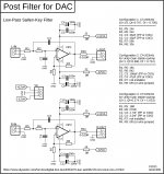
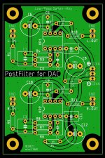
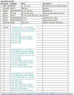
Post Filter for DAC - Low-Pass Sallen-Key
Low-Pass active post filter after the DAC (after I/V) is used to smoothen the sharp samples at the DAC output due to the digital code converted to analog levels. In other words it reconstructs and band limits the DAC output signal 😎
It may be helpfull to remove a high frequency generated from digital side.
As always, the sound will be certainly colored according to the components used (opAmp and capacitors)
Attachments
#1431
Everything you need to know is that R8/R9 value sets the output voltage from the I/V (1k4 == 1.4Vp, 2k5]
Hi miro,
I am using 1k5 for R8/R9 and my oscilloscope tells me that I have 3 V peek to peek at maximum volume. Am I supposed to see 1.5Vp instead? How is the math done?
Thanks

- Home
- Source & Line
- Digital Line Level
- DAC AD1862: Almost THT, I2S input, NOS, R-2R