Ultra-linear us not all that linear as it sounds, since grid2 does not have the same transfer factor (power law) as grid 1. So effectively corrupting the N Fdbk.
"UltraLinear" is an artifact of its time. It allowed some contemporary valves, new at that time, to survive with G2 idling voltages at B+, in an era of horsepower racing. Also eased source impedance issues for the output transformers, in an era before feedback taken from the primaries was a thing.
Do we still care about it today, with our current perspective of other (more linear) feedback taken from the primaries, and very desirable hi-performance valves originally built for much lower G2 voltages? Horses for courses I guess.
All good fortune,
Chris
In my small experience, I find UL useful in instruments amplification, where you can "define" the compression effect at higher volumes (with low % of UL and loadlines touching the Pdmax curve), often demanded by players. It also makes the amp simpler and with the right DF for the purpose.
In my even smaller experience in Hi-Fi, I like its simplicity to supply g2, but I don't find it is enough alone, and it needs help by some dB of nfb taken from the primary. I hope to have the possibility, in a pair of weeks, to do some more tests on another kind (to my small experience very promising) of feedback from the secondary.
In my even smaller experience in Hi-Fi, I like its simplicity to supply g2, but I don't find it is enough alone, and it needs help by some dB of nfb taken from the primary. I hope to have the possibility, in a pair of weeks, to do some more tests on another kind (to my small experience very promising) of feedback from the secondary.
Referring to the original post: it is not ultralinear. It simply creates a fixed g2 voltage, so it is a pentode circuit.
The grid of 6GC7 is connected to a 100k+100k voltage divider from the plate of the EL86 to ground, so it is a 50% UL configuration. How could g2 be fixed?
Take a resistor combination of HT (R1), Ground (R2) and out plate (R3). The input to the buffer should not go above HT at max plate swing (say 2*HT) for the buffer to work properly.
G2vdc = HT * (R1 || R3) / ((R1 || R3) + R2)
%UL = R3 / (R1 + R2 + R3)
G2vdc = HT * (R1 || R3) / ((R1 || R3) + R2)
%UL = R3 / (R1 + R2 + R3)
Last edited:
Ah indeed. I wonder how does it work in practice.The grid of 6GC7 is connected to a 100k+100k voltage divider from the plate of the EL86 to ground, so it is a 50% UL configuration. How could g2 be fixed?
i said skipping, but meant rectifying instead.I think you have a point. But if you mean that it will skip every positive halfwave completely, than I disagree.
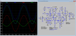
signal baseline at anodes will be at supply dc voltage, let´s pretend it´s 2v.
as you see, signal on anodes will swing above and below dc supply voltage. (picture)
on real ul tap signal would be same, but proportially smaller... according to ul tap size (40%)
THEREFORE i am asking, how can you provide positive peaks above dc voltage baseline, from simple follower ?
simply, you can´t...
there is one trick- you must use higher dc voltage for the follower. only then it works.
Presumably this is only an issue if you intend to replicate the case where G2 DC voltage should be close to anode, but the G2 signal voltage is in proportion to the UL tap. In the case of tubes that have a lower G2 voltage requirement, e.g. 807, then the required swing will be available because of the anode resistor on the cathode follower.
Having the g2 voltage go above B+ just makes the tube harder to turn off when it is supposed to turn off. But would cause a non-linearity for any class A portion. TV Sweeps using 150V g2 and > 300V B+ would seem to be the natural fit here.
But all this "ultra-linear" BS just causes tubes to have no strong current capability when it is most needed.
The UL taps should be used for N Fdbks to the driver stage, where it does not harm output tube performance. And will give better linearity when compared directly with input signal, rather than thru the g2 non-linearity.
Last edited:
PFL200,
Nice schematic. Thanks!
Looks like it has 'Attenuated' Schade negative feedback.
Cute idea.
Nice schematic. Thanks!
Looks like it has 'Attenuated' Schade negative feedback.
Cute idea.
What is the benefit compared to a simple shade with driver's plate connected to OPT primary and B+ with two resistors, as others do?
Here it is explained how Schade feedback (if this is what is meant by it) lowers the AC-load of the preceding stage: Fundamentals Of Radio Valve Technique : Deketh, J : Free Download, Borrow, and Streaming : Internet Archive
I would think that the feedback in the schematic in post #30 also lowers the AC-load of the preceding stage but I can't figure out if it does this to a lesser extent than Schade feedback does (with the amount of feedback being the same for the two situations).
I would think that the feedback in the schematic in post #30 also lowers the AC-load of the preceding stage but I can't figure out if it does this to a lesser extent than Schade feedback does (with the amount of feedback being the same for the two situations).
Hard to see much difference between that pseudo UL tap N Fdbk and the usual shunt "Schade" from the plate.
One subtle difference could be the drive signal corruption level to the N Fdbk. Usual shunt "Schade" develops some unintentional 2nd H from the grid voltage variation affecting the voltage across the N Fdbk resistor (and so affects the current thru it). While the tapped pseudo UL maybe adjusts its tap ratio slightly to compensate some for this, due to the variation in loading? (then again, maybe not, it is a linear R network) Any better ideas why they would add more resistors? Maybe the R divider provides some protection to the grid in case of flashover across the N Fdbk resistor, by attenuating the plate V variation.
One subtle difference could be the drive signal corruption level to the N Fdbk. Usual shunt "Schade" develops some unintentional 2nd H from the grid voltage variation affecting the voltage across the N Fdbk resistor (and so affects the current thru it). While the tapped pseudo UL maybe adjusts its tap ratio slightly to compensate some for this, due to the variation in loading? (then again, maybe not, it is a linear R network) Any better ideas why they would add more resistors? Maybe the R divider provides some protection to the grid in case of flashover across the N Fdbk resistor, by attenuating the plate V variation.
Last edited:
If you use the Schade negative feedback method, you have the driver plate resistance rp, the driver resistor RL, the Schade feedback resistor. That is all fed by the output tube rp, the output transformer's primary reactance which varies with frequency, and the additional varying impedance of the primary caused by the loudspeaker's frequency dependent impedance (or caused by the load resistor reflected impedance to the primary, when running tests).
The circuit in Post # 30 only changes the following:
1. The driver load resistor RL 'goes away', and is replaced by the now dual function resistor: driver RL / Schade feedback resistor (2 functions combined into 1 resistor).
2. The driver Schade feedback resistor is driven by the 2 resistor divider.
It should be noted that this different circuit feedback resistor is no longer driven directly from the output tube plate/primary node, it is driven from the resistor divider.
The result of all of that changes the impedances that the various parts of that circuit see, no matter how creative you are at picking the resistor values (because only one of the divider resistors is direct connected to the output tube plate/primary node).
And, it should be noted that circuit in Post # 30 uses the output tube in Pentode/Beam Power mode.
That circuit is Not Ultra Linear. The output tube screen goes directly to B+
It also should be noted that the Schade negative feedback resistor, and the Post # 30 negative feedback resistor put a heavier load on the driver tube plate, than no negative feedback to the driver plate.
(Schade circuits, and Post # 30, place a Lower impedance on the driver plate, not a higher impedance).
Those are the only changes to that circuit versus a traditional Schade feedback circuit.
That is how I view the differences.
Last edited:
Thank you all for your replies,
in SE applications I've most often seen the shunt feedback resistor together with the standard plate load, that's why I can't see the difference with this system.
What I'd do compared to all schematic I've seen, is split the shunt feedback resistor (a-g1 nfb) in two resistors in series due to the high swing the anode can have (not to exceed resistor's maximum voltage across it).
I have found another iteration of this design, but taken to the extreme where there is no drive to the grid at all.
The article is here ...
PL36 SE amp
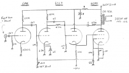
The author experimented with many different ways to try and get some linear behaviour out of a 6CM5, which is an equivalent of a PL36. The best operating point was to tie the grid to the cathode, set g2 to +25V with the anode at 250, and drive g2, also using a 6CG7 in a very similar screen drive configuration to the circuit at the start of this thread.
The clipping issue mentioned by an earlier poster, due to the anode of the cathode follower being at a similar potential to the out put tube, is solved in this circuit by biasing the cathode of the follower with a negative supply.
The article is here ...
PL36 SE amp
The author experimented with many different ways to try and get some linear behaviour out of a 6CM5, which is an equivalent of a PL36. The best operating point was to tie the grid to the cathode, set g2 to +25V with the anode at 250, and drive g2, also using a 6CG7 in a very similar screen drive configuration to the circuit at the start of this thread.
The clipping issue mentioned by an earlier poster, due to the anode of the cathode follower being at a similar potential to the out put tube, is solved in this circuit by biasing the cathode of the follower with a negative supply.
Attachments
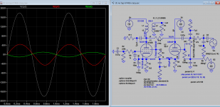
This version is as close as I can get with reference sch in post #7, the distortion is much less with lower G2 and G2 voltage, but no negative supply required and reduced driver plate supply as the driver is self biased to cover the input drive level. Thd 2% @9W Pout, input 100V-p.
Attachments
- Home
- Amplifiers
- Tubes / Valves
- Ultralinear SE amp with no UL tap