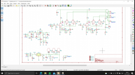

At first glance, I'd say the output tubes are too close together - a reasonable rule of thumb is at least one tube diameter between them.
The details of the schematic are a little hard to make out
The details of the schematic are a little hard to make out
Tube socket top right pin 5 and 9 state GND but are connected to power? However the pins are a short out?
Edit: nope that looks ok - U1 and it has a centre grounded heater.
Edit: nope that looks ok - U1 and it has a centre grounded heater.
Last edited:
pdf of schematic.
So they are push pull with a centre tapped output transformer?
Yep that's correct. A simple LTP. The transformer is not completely flat but I did prototype with a 240v - 12v toroid which was worse. The NFB should sort this out.
9 is screen between two halves of ecc88. 4 and 5 are heaters wired in series for 12.6v. Its easier to generate 12.6v DC than 6.3v. Just checking... The output tubes are too close it will look a bit silly (good point) but I just want to check Kicad and my understanding. They will heat each other up a bit more but are not power tubes.
Last edited:
OCD would have me rotating to ecc88s by 90 degree so the plates radiate away from each other. But that’s just me 🙂
Do you you have a bode plot?
I see the output impedance is 3R or higher, for 32R you may be loosing some bottom end.
I see the output impedance is 3R or higher, for 32R you may be loosing some bottom end.
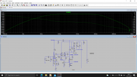
That's decent.
Only remaining concern I have is the startup and the heaters. I'm assuming that the tubes will take different times to heat and thus resistances may cause higher current down one side of the parallel'd heaters due to the imbalance. Unfortunately that's hard to model given it's depending on the individual tube in the socket.
What are you volume controlling from? Pre-input or between the input and the LTP? Just curious given the 12AX7 as it's not a tube I've used. Although the bode plot shows it's fine (and I assume in real life it's fine) that small12AX7A current has a lot to drive with a 1uF after it.
On the kicad schematic C5 & C7 shows 100V caps. Given you've a 100V DC amp and in theory the signal should stay within that.. I'd be tempted going larger with 150-200, even 250V. Also what's the ESR you have used in the model? I tend to use 55mOhm for the FKP1 0.22uF, but something more for MKP10 but I can't find the last schematic I used them.
Last edited:
The two ECC88 heaters are in series, the 12AX7 is in 12v config. My experience is as long as you use the same type of ECC88 for both all is OK. Even if you plug in one hot and one cold the hot one get bright before the cold one warms up - but it does not damage the tube at least in the short term. The 12AX7 is just driving the high input impedance of the ECC88 as long as the grid does not conduct so the ESR is not such a concern. At cold there is about 95V across the 1uF but this drops 50V during normal operation. The volume control is before the input and will be 22k log.
Gone for gold and placed an order with JLCPCB - all seemed to go through easily. Thanks for everybody's help. Nick since you are in the UK if you wish to send your address on the private post I can post you a PCB, I'll check its OK first mind!
I'm struggling somewhat about the position of the reference diode in your HT regulator, as I'd have expected it in Q5's emitter lead. What's the reason for swapping D8 and R25?
Best regards!
Best regards!
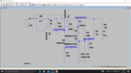
What's the advantage of referencing the reference diode to the output voltage instead of gnd?
Best regards!
Best regards!
Could you sketch what you were thinking. It's the easiest way of getting good open loop gain in Q2.
I'm struggling somewhat about the position of the reference diode in your HT regulator, as I'd have expected it in Q5's emitter lead. What's the reason for swapping D8 and R25?....
M1 is not a conventional follower. It inverts. So puzzle on from there. Something has to be swapped. D8/R25 (Q5's "+" and "-" inputs) looks valid.
One question did you model cross talk? Looking I can see RC filters on the output just wondering how effective it was.
I’ll message tomorrow.
I’ll message tomorrow.
I did see a bit of crosstalk at LF. But only if the output was clipping very hard. The HT is regulated so no issue there, seems to be U3 grid conduction causing the voltage at D2 to change and getting into the other channel. At HF its probably sharing the 12ax7 between the plates. I suppose you could make it all separate.
- Home
- Amplifiers
- Tubes / Valves
- Headphone schematic and layout