While building a replica of a Marantz 7C and now working on the last phase of the build (tone amp), I became interested in what type of tone control circuit was utilized and if Saul Marantz and engineers he was associated with in the 50's were already knowledgeable in tone control (within feedback loop) design or if they would not have had the necessary technical expertise without the work of Baxandall. Or, is there anything in the 7C tone amp design that could even be remotely related to Baxandall's designs?
I had the pleasure of reading the thread by JoeAlders (Bass-Treble potentiometers in Baxandall tone control) and it peaked my interest in the subject matter even more.
Looking forward to any feedback on this interesting subject.
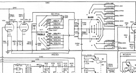
I'm attaching a snip of the Marantz 7C original circuit for reference.
I had the pleasure of reading the thread by JoeAlders (Bass-Treble potentiometers in Baxandall tone control) and it peaked my interest in the subject matter even more.
Looking forward to any feedback on this interesting subject.
I'm attaching a snip of the Marantz 7C original circuit for reference.
Attachments
Last edited:
Not really. It lacks Baxandall's concept of balancing the forward and NFB paths. Instead it either introduces series RC into the NFB to provide cut, or shunts it to ground to provide boost.
Interesting to hear this. One would wonder why Marantz and Mac would have chosen a much more complicated and labor intensive design in the 50's when the Baxandall circuits appear to be much simpler and far less of a parts count. Just looking at the labor required to construct those rotary tone selectors looks daunting.
You mention shunt to ground to provide boost with The Marantz circuit. Can you elaborate on this. In looking at the treble control, in rotating counterclockwise from the center position (5 positions), aren't these all shunting to ground? I had assumed the schematic representation would be showing clockwise rotation to be boost and CCW cut.
You mention shunt to ground to provide boost with The Marantz circuit. Can you elaborate on this. In looking at the treble control, in rotating counterclockwise from the center position (5 positions), aren't these all shunting to ground? I had assumed the schematic representation would be showing clockwise rotation to be boost and CCW cut.
Considering the treble control, it determines what is connected to the NFB network via the 680R resistor. All the CCW positions provide boost by shunting treble NFB to ground. All the CW positions provide series RC in the NFB network to provide cut.
The bass control is more complex. The top switch determines what is interposed in the NFB to provide boost: the bottom switch determines what is interposed in the output line to provide passive cut.
The bass control is more complex. The top switch determines what is interposed in the NFB to provide boost: the bottom switch determines what is interposed in the output line to provide passive cut.
I believe that the mechanical aspect should be separated from the electronic one, today they continue to manufacture and sell stepped resistor controls instead of continuously variable potentiometers. (For example, Khozmo, used by 300B fans)
High Quality Audio & Industrial Attenuators
A stepper control can replace the classic rotary in a Baxandall circuit perfectly.
Apparently Baxandall's upgrade was due to it introducing less distortion if I understood the following correctly. Beyond the physical connection, which is secondary.
Baxandall - an overview | ScienceDirect Topics
Like all frequency-selective feedback amplifiers, the Baxandall tone control has an input impedance that changes horribly with frequency, so unless the preceding stage has plenty of feedback and current capability, this frequency-dependent loadline is converted into frequency-dependent distortion, which is almost certainly why tone controls are so frequently vilified. It’s not that the tone control stage itself distorts, but it makes the previous stage distort, and worse, it causes frequency-dependent distortion that is especially fatiguing because it forces the ear to attempt to reject a complex pattern that changes with frequency rather than a simple fixed pattern. The Baxandall tone control stage must be preceded by a stage capable of driving a changing impedance with constant or negligible distortion.
Given that the Baxandall tone control inverts polarity, it would be useful if the preceding stage also inverted polarity because this would restore correct polarity. Combined with the current drive and distortion requirement, this suggests that the ideal preceding stage might be another unity-gain pentode inverter identical to that in the tone control. Admittedly, this becomes expensive in HT current, but that’s the price of a decent tone control. Self [5] offers a much fuller discussion of the relative merits of the different forms of Baxandall tone control, so this author will simply content himself with presenting a version that he believes is appropriate for domestic reproduction
Considering the treble control, it determines what is connected to the NFB network via the 680R resistor. All the CCW positions provide boost by shunting treble NFB to ground. All the CW positions provide series RC in the NFB network to provide cut.
The bass control is more complex. The top switch determines what is interposed in the NFB to provide boost: the bottom switch determines what is interposed in the output line to provide passive cut.
This should help me figure out which rotation sequence I need to follow in order to end up with my rotary switches boosting in he CW rotation. I'm going to assume the schematic representation view of the rotary switches is from the rear since in that view, boost is in the CCW direction?
I believe that the mechanical aspect should be separated from the electronic one, today they continue to manufacture and sell stepped resistor controls instead of continuously variable potentiometers. (For example, Khozmo, used by 300B fans)
[/I]
In my previous post I questioned why Marantz would have incorporated into the C7 what appears to be a much more complicated tone control arrangement compared to the Baxandall circuits but in looking over the schematic of the earlier Consolette Model 1 (see image), it seems they had used the Baxandall or something similar and scrapped it for the stepped RC arrangement a few years later in the C7.
Attachments
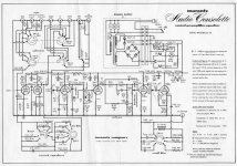
That's not a Bacandall tone control either. No negative feedback; shunted to ground; and unequal capacitor values. It is the James 1949 tone control. Purely passive.
You don't have to assume anything about the view. Just build it the way you want it.
You don't have to assume anything about the view. Just build it the way you want it.
Last edited:
I hadn't given the schematic a decent look over and I now see the lack of negative feedback.
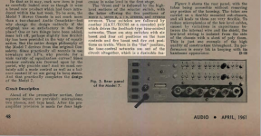
I found this review of the Marantz 7C in a 1961 Audio magazine clip which might be of interest regarding their mention of the tone controls boost and cut details.
I found this review of the Marantz 7C in a 1961 Audio magazine clip which might be of interest regarding their mention of the tone controls boost and cut details.
Attachments
- Home
- Source & Line
- Analog Line Level
- Marantz 7C tone amp design related to Baxandall?