The P-P FB Networks look to be frequency selective, altho I've done none of the math. Just a quick eyeball observation.
So back to manual labor for today, completely non-electronic.🙂
So back to manual labor for today, completely non-electronic.🙂
C21 & C22 would be my primary suspects, what do you think they are doing ?
470pF looks awfully big ... 47pF or take them out altogether for a try
also 470k as cathode follower load resistor is huge, I' d say it should be much lower, but then a 12ax7 is too whimpy and low gm
if you'd provide the .asc file (zipped) we could play with it easily ..
470pF looks awfully big ... 47pF or take them out altogether for a try
also 470k as cathode follower load resistor is huge, I' d say it should be much lower, but then a 12ax7 is too whimpy and low gm
if you'd provide the .asc file (zipped) we could play with it easily ..
C21 & C22 would be my primary suspects, what do you think they are doing ?
470pF looks awfully big ... 47pF or take them out altogether for a try
also 470k as cathode follower load resistor is huge, I' d say it should be much lower, but then a 12ax7 is too whimpy and low gm
if you'd provide the .asc file (zipped) we could play with it easily ..
Sure, have a look, the archive also contains a design less fancy that seems to work well at least, which is where I started from, libs etc. are also included.
Attachments
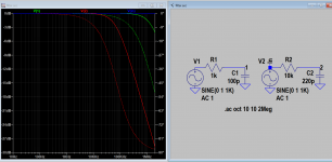
I run the sim files you post but I didn't manage to complete and my CPU > 80 deg. I manage to complete sim when NFB is disable. So I find out the open loop gain is about 3000, and then reduced by NFB about 10 times. an overall gain of 300. Look very hot to me, is it a guitar amp? It may oscillate in actual build as the gain is so high. Also 3db freq. response with R17/C11, 10k/220p is about 13khz in the input, usually 1k/100p, 1Mhz.
Last edited:
Also 3db freq. response with R17/C11, 10k/220p is about 13khz in the input, usually 1k/100p, 1Mhz.
I thought about that, too, but ...
f=1/(2*pi*R*C) = 72kHz without miller cap and about 48kHz including miller cap ... not so ?
Last edited:
I sim'd the "trans" version, and it confirmed that the 470pF C21/C22 severely limit the slew rate causing the observed triangle distortion.
And yes, Koonw is right, when those caps a lowered the amp oscillates even in sim.
Which is no surprise, 3 gain stages ... one too many.
Assume, those caps were added to tame those oscillations, replacing one evil with another.
And yes, Koonw is right, when those caps a lowered the amp oscillates even in sim.
Which is no surprise, 3 gain stages ... one too many.
Assume, those caps were added to tame those oscillations, replacing one evil with another.
I sim'd the "trans" version, and it confirmed that the 470pF C21/C22 severely limit the slew rate causing the observed triangle distortion.
And yes, Koonw is right, when those caps a lowered the amp oscillates even in sim.
Which is no surprise, 3 gain stages ... one too many.
Assume, those caps were added to tame those oscillations, replacing one evil with another.
Yes, which is to be expected I guess, but it isn't about the number 0f gain stages really, you just need to be careful how you implement them and what the net total gain and phase is across them.
- Home
- Amplifiers
- Tubes / Valves
- KT88 push pull cathode follower?