The small-signal loop gain/phase are fine. Phase dips below ten degrees at midband, typical of TPC. When it clips, all that goes out the window.
This is the best paper I've seen on the subject, but at 75 pages, it's a slog and I haven't tried to digest it yet.
https://www.electronicsworld.co.uk/wp-content/uploads/2020/04/amps.pdf
This is the best paper I've seen on the subject, but at 75 pages, it's a slog and I haven't tried to digest it yet.
https://www.electronicsworld.co.uk/wp-content/uploads/2020/04/amps.pdf
I had circuit with npn ef VAS that had same clipping issues, just other polarity of course.
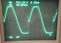
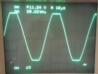
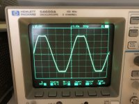
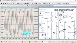
Here is a scope grab before and after adding a single BAV21. (111Vp-p (x10 probe))
Been 6 yrs and the amp is still going well.
Regards
Here is a scope grab before and after adding a single BAV21. (111Vp-p (x10 probe))
Been 6 yrs and the amp is still going well.
Regards
Attachments
That's not bad for 20 kHz! I assume that was a Lin (aka blameless) topology with the current source load on the negative rail?
Why don’t you put a loop gain/phase plot up.
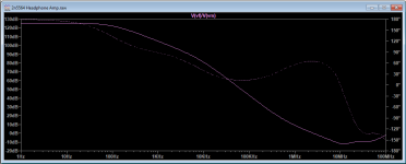
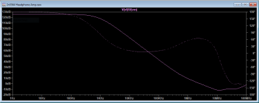
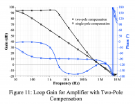
Simulated Bode plots with and without the clamp. The effect of diode capacitance is evident.
Clipping was perfect with the clamps in place, but at what cost to sound quality?
Attachments
Last edited:
You have c. 70 dB feedback at 20 kHz with the clamps (which is high) and c. 80 dB without the clamps (a bit higher). As I mentioned a few posts back, in a practical amp you have higher parasitic capacitances around the board than the diode capacitance so what the loop gain plot actually looks like in practice without actually measuring it is anyone's guess. The main thing is to close it at a decently low frequency and ensure you have plenty of gain and phase margin which you have done. The difference between 70 dB feedback at 20 kHz and 80 dB will not effect sound quality.
One thing you may want to try is loading the output with a bit of capacitance to ensure it remains stable - with a 2-3 metre headphone cable its probably a few hundred pF but personally I'd check it with up to a few nF - but that's a design choice you have to make.
Put your mind at rest and do some measurements. I suspect your 1 kHz distortion will be very low because of the high loop gains involved. If you use a sound card, you can do an IMD test (19kHz + 20 kHz with both signals at about -10 dBV) which will give you a clear indication of HF linearity - the 1 kHz intermod tone should be -100 dBr or better. You can do the tests with and without the clamps.
You do have a zero out at about 10 MHz - do you have a cap across your feedback resistor? You may want to play with that a bit to tame it but it doesn't look like its a problem in any event looking at your scope shot which looks pretty clean with the clamps.
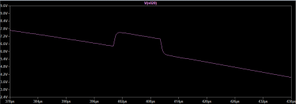
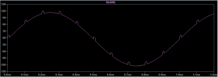
One other sim you can try is the Bowes test. Place two voltage sources in series. Set the one to 100 Hz sine with an input voltage that takes the output to within a few % of each rail - ie 200-300mV before clipping. Set the second voltage source to 50mV square wave. Run the sim for a few cycles then zoom into the square wave at the sine peaks. It should be clean with no overshoot and look the same as the input signal. The sine wave is exercising the device parameters over the full operating envelope and the square wave stimulus is looking at the loop stability.
Onward and upward!
One thing you may want to try is loading the output with a bit of capacitance to ensure it remains stable - with a 2-3 metre headphone cable its probably a few hundred pF but personally I'd check it with up to a few nF - but that's a design choice you have to make.
Put your mind at rest and do some measurements. I suspect your 1 kHz distortion will be very low because of the high loop gains involved. If you use a sound card, you can do an IMD test (19kHz + 20 kHz with both signals at about -10 dBV) which will give you a clear indication of HF linearity - the 1 kHz intermod tone should be -100 dBr or better. You can do the tests with and without the clamps.
You do have a zero out at about 10 MHz - do you have a cap across your feedback resistor? You may want to play with that a bit to tame it but it doesn't look like its a problem in any event looking at your scope shot which looks pretty clean with the clamps.
One other sim you can try is the Bowes test. Place two voltage sources in series. Set the one to 100 Hz sine with an input voltage that takes the output to within a few % of each rail - ie 200-300mV before clipping. Set the second voltage source to 50mV square wave. Run the sim for a few cycles then zoom into the square wave at the sine peaks. It should be clean with no overshoot and look the same as the input signal. The sine wave is exercising the device parameters over the full operating envelope and the square wave stimulus is looking at the loop stability.
Onward and upward!
Last edited:
You have c. 70 dB feedback at 20 kHz with the clamps (which is high) and c. 80 dB without the clamps. As I mentioned a few posts back, in a practical amp you have higher parasitic capacitances around the board than the diode capacitance.
The difference between 70 dB feedback at 20 kHz and 80 dB will not effect sound quality.
You've closed the loop at about 2-3 MHz which for the type of circuit you have is ok (A bit high for a full power amp, but this is a headphone amp).
Put your mind at rest and do some measurements. I suspect your 1 kHz distortion will be very low because of the high loop gains involved. If you use a sound card, you can do an IMD test (19kHz + 20 kHz with both signals at about -10 dBV) which will give you a clear indication of HF linearity - the 1 kHz intermod tone should be -100 dBr or better.
You do have a zero out at about 10 MHz - do you have a cap across your feedback resistor? You may want to play with that a bit to tame it but it doesn't look like its a problem in any event looking at your scope shot which looks pretty clean with the clamps.
Onward and upward!
Thanks for the analysis. All bets are off without measurements, as you suggest. I don't remember if I said this here or elsewhere, but I was thinking seriously about buying a QuantAsylum analyzer. This is still a possibility, but they're out of stock indefinitely at the moment thanks to the ongoing parts crunch. I need to think about whether I want to spend the money on a lab-grade capture box.
Above all, I was simply amazed these circuits were stable at all. When I was in college, with paper-and-pencil analysis, I tried building a no-holds barred amplifier and never managed to tame it. This was back in the days when we made resistors by charring silk thread in an oven, and cars had cranks on the front.
HPA1 was also my first try with TPC. Up until recently, I didn't understand TPC very well and was skeptical of it. It works, so SPICE must be worth something.
I used the technique of inserting an AC probe in the feedback loop to generate these Bode plots. The rising response above 10MHz bothered me so I tried simulating the end-to-end open-loop response the usual way without the probe and didn't see the increasing response. On further analysis, I concluded that signal coupling across the input devices, from the non-inverting input and back out of the inverting terminal, is responsible for the HF rise in the plots here. You can see it if you plot the transfer function across the feedback network, which does not act like a constant voltage divider when connected to the inverting input. I'm not sure this is actually relevant to the stability analysis, but it's a nuisance. Dymond and Mellor's TPC paper shows a similar feature in their Bode plot. I can't find any other explanation for the rising response, so I just ignore it.
The diamond buffer has an RF peak around 10 MHz. In HPA2, I added a lag compensation network at the input to the buffer that improves the gain margin before the rise starts up again. HPA1 does not have this network. The tuning is probably hit-or-miss given the frequency and the real-world variables involved.
70dB of NFB seems absurd and I would normally dismiss the need for it. But if the amp tolerates that much feedback, why not? I agree, it seems unlikely the tiny diode capacitance would make an audible difference, and yet here I am preferring the sound of one amp to another, when conventional wisdom says the distortion should be well below the threshold of audibility.
Another possibility is that the diodes are affecting the sound somehow, but for an entirely different reason. Possibly the fault lies with the amplifier itself and not the diodes.
The most complex part of the signal processing chain is between our ears, and who knows what's going on there? So I don't know what to say, except that I had a strong preference for the HPA2 versus the HPA1 with clamp diodes, and now, without the clamps, I find them more or less to sound the same. There are people who will tell you with a straight face they can hear the difference between black and gray hookup wire.
Attachments
One other sim you can try is the Bowes test. Place two voltage sources in series. Set the one to 100 Hz sine with an input voltage that takes the output to within a few % of each rail - ie 200-300mV before clipping. Set the second voltage source to 50mV square wave. Run the sim for a few cycles then zoom into the square wave at the sine peaks. It should be clean with no overshoot and look the same as the input signal. The sine wave is exercising the device parameters over the full operating envelope and the square wave stimulus is looking at the loop stability.
Good suggestion. I recently bought a function generator, but decided against a far more capable Siglent in favor of vintage Agilent... just because. I knew that's the one test I would want to, but can't do with the Agilent. Maybe I'll rig up a circuit to generate that waveform sometime.
Anyway, SPICE doesn't show anything wrong, for what it's worth. Results are about the same with or without the diode. This is with the ultrasonic filter. If I remove it from the sim, there's some mild overshoot on the pulse edges, but nothing bothersome.
Attachments
Thanks. I don't have many answers, but hopefully my findings will prove useful to someone.
To summarize, it seems like a lot of people have run into problems with the beta-enhanced VAS and clipping. The Baker clamp solves the problem neatly on the bench. The Blameless crew strongly discourage using clamps because of the increase in measured distortion. Subjectively, the jury is still out, but I thought I heard a problem. Others use clamps and don't find them to degrade the sound.
The long paper I linked above suggests that the cascode VAS may be a better solution. It clips cleanly without needing clamps, and the distortion is almost as good. There are also other ways to clamp (see http://www.cordellaudio.com/papers/MOSFET_Power_Amp.pdf, which is the basis of my HPA2 project) that might be preferable.
I'm still thinking about where I might go next. I'll post updates in my other thread (New Headphone Amplifier Design) when I have news to report.
My 2 cents…
Adding a resistor to the collector of the VAS buffer (emitter follower) is not a good practice, and may be looked as a band aid to an already compromised design (stability wise).
First, the resistor will drop some voltage, depending on the transistor instantaneous collector current. This voltage drop is therefore signal dependent and leads to a variable Vce, therefore the Early effect will show its ugly head. The distortions of an otherwise distortion free emitter follower will increase significantly.
Secondly, from a stability perspective, a collector resistor may not always help. The discussion is too complex to carry here, enough to know that the collector resistors introduces a zero in the forward gain. When the feedback loop closes it is not obvious how this zero will move, in particular with amps designed with high loop gains. It may actually compromise the gain margin in the loop gain. When I’m saying “feedback loop” I mean in this particular case less the global feedback loop, but mostly the local Miller loop (or whatever two pole compensation is used). It is the local compensation feedback loop that is mostly affected.
Bottom line, I would avoid that resistor and use VAS current limiting, which will also protect the emitter follower. If the amp is marginally stable, I would rather lower a little the unity gain loop frequency (that is, adjust the compensation) than adding the resistor. In my practice, I always prefer to start with the most linear open loop amplifier possible, then add as much global feedback as possible, to keep the amp rock solid stable.
Last edited:
A resistor in the collector of the VAS buffer markedly reduces slew rate, particularly a resistor drop >10V.
But a small resistor, dropping no more than a couple of volts, limits the current should the base buffer go high, saving the EF. This does not change the sound quality and minimally reduces slew rate. The variation at the collector under operation is very small, particularly if the VAS current is fixed.
Early effect is certainly is an issue for the EF, but if the Vce varies only a few millivolts for a drop of say 40V it is almost negligible.
I agree with Syn08 that that collector resistor adds a new local feedback path, complicating things, and taking away the notional purity of the emitter follower. The Baker clamp is simple and elegant, but for me it does something bad to the sound, though I can't prove that. Others object to the clamp because of its small theoretical effect on distortion. Self prefers the VAS current limiter transistor, and I guess deliberately ignores the clipping instability. That's a large-signal loop feedback problem that I don't have the analytical skill to solve. It could be I'm trying to apply more global feedback than this circuit will bear under extreme signal conditions. Or maybe it doesn't matter in practice.
I want to get good sound while satisfying my personal sense of design elegance. Different people will arrive at their own compromises. Sorry for being so fruity about it, but you have to admit, the whole subject is pretty esoteric by most standards.
I want to get good sound while satisfying my personal sense of design elegance. Different people will arrive at their own compromises. Sorry for being so fruity about it, but you have to admit, the whole subject is pretty esoteric by most standards.
My 2 cents
Adding a resistor to the collector of the VAS buffer (emitter follower) is not a good practice...
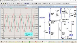
I simulated VAS baffer collector resistor influence on distortion with two amp types, CFA and VFA with different VAS emitter resistor values 100R and 16R.
CFA result, full output swing 80 Vpp, with collector resistor of 6k8 simulated THD is 1.21 ppm and collector voltage swing is 0.17 Vpp.
Even with quite low Early voltage of 57 for used transistor (2SA970, Vaf=57) there is just small THD increase of 1.6% (with no collector resistor THD is 1.19 ppm).
VAS emitter resistor was set to 100R
Regarding SR, there is drop from 270 V/usec to 237 V/usec.
VFA result, amp with TT output transistors, full output swing of 80 Vpp woth collector resistor of 1k simulated THD is 1.01 ppm and collector voltage swing is 0.018 Vpp.
Transisor used in simulation is KSA992 with Vaf of 144 and there is no THD increase compared with no collector resistor. VAS emitter resistor was set to 16R.
SR does not change with or without this resistor, even with increase value to 6k8.
My opinion is that there is much more benefit using that overload protection resistor than harm. Some years ago I built some Self blameless amps (Self never used that resistor) and had a problem of burning VAS and helper transistor. After introducing that resistor it never happened again.
Attached some simulation plots and some real measurements on my CFA amps, all with that protection resistor in.
Adding a resistor to the collector of the VAS buffer (emitter follower) is not a good practice...
I simulated VAS baffer collector resistor influence on distortion with two amp types, CFA and VFA with different VAS emitter resistor values 100R and 16R.
CFA result, full output swing 80 Vpp, with collector resistor of 6k8 simulated THD is 1.21 ppm and collector voltage swing is 0.17 Vpp.
Even with quite low Early voltage of 57 for used transistor (2SA970, Vaf=57) there is just small THD increase of 1.6% (with no collector resistor THD is 1.19 ppm).
VAS emitter resistor was set to 100R
Regarding SR, there is drop from 270 V/usec to 237 V/usec.
VFA result, amp with TT output transistors, full output swing of 80 Vpp woth collector resistor of 1k simulated THD is 1.01 ppm and collector voltage swing is 0.018 Vpp.
Transisor used in simulation is KSA992 with Vaf of 144 and there is no THD increase compared with no collector resistor. VAS emitter resistor was set to 16R.
SR does not change with or without this resistor, even with increase value to 6k8.
My opinion is that there is much more benefit using that overload protection resistor than harm. Some years ago I built some Self blameless amps (Self never used that resistor) and had a problem of burning VAS and helper transistor. After introducing that resistor it never happened again.
Attached some simulation plots and some real measurements on my CFA amps, all with that protection resistor in.
Attachments
-
 test enhaced VAS-0.1R.jpg242.9 KB · Views: 156
 -
 test enhanced VAS-6k8.jpg206.2 KB · Views: 159
 -
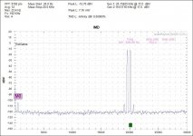 100W CFA ClassA+ClassB IMD.jpg85.7 KB · Views: 152
 -
 100W CFA ClassA+ClassB-SMica- THD1.jpg94.8 KB · Views: 141
 -
 full rated power into 8. 20KHz. .002% THD.jpg291.6 KB · Views: 129
 -
 THD+N Freq 50W 8R-Richard measurement.jpg164.1 KB · Views: 113
Interesting data. Thanks so much for posting.
Time permitting, I should build a test amp where I can easily switch between the different forms of protection and listen for myself.
I also really need to think about getting an audio capture box or card so I can measure these things myself. It's almost hopeless to do this work without measurement capability.
I have a half-built VNA project sitting in a box in the closet. If I ever finish it, it has enough dynamic range to make gain/phase plots possible. Too many projects...
The closed loop distortion fundamentally depends on the available loop gain. You are using unusual high ULGFs, so no surprise you got a small delta in the closed loop distortions.
Not to mention my usual distrust in spice simulation of large signal behaviour, in particular at these distortion levels.
Not to mention my usual distrust in spice simulation of large signal behaviour, in particular at these distortion levels.
The closed loop distortion fundamentally depends on the available loop gain. You are using unusual high ULGFs, so no surprise you got a small delta in the closed loop distortions.
Not to mention my usual distrust in spice simulation of large signal behaviour, in particular at these distortion levels.
From simulation was obvious that collector voltage of the VAS help transitor does not fluctuate much, just some hundred millivolts even with VAS emitter resistor of quite high value 100R, so no influence of Early voltage.
Here I showed some real measurement, not so good as simulated but still very good.
It would be interesting to simulate the effect on distortion of just the VAS in isolation.
Under normal operating conditions, the changes in collector current of the helper transistor are miniscule - and especially so where you have high loop gains as is the case with the OP's design. You can easily check this in a sim.
A 1k resistor in the collector of a helper transistor will drop a few hundred mV at worst. If you are getting many volts of drop across that resistor in a standard VFA with 1k then I'd venture that you have serious compensation problems - the input signal rise times should never be fast enough to allow large drops across this resistor during the time it takes the loop to react.
You only need some capacitance and inductance and 180 degree phase shift across any two ports and you have the potential for oscillation - so its not just a simple case of negative resistance being reflected back into the base. Cordell discusses this in some general terms in his book where he talks about the Colpitts problem with followers. The small collector resistor acts to damp that, the same way a base stopper does.
I won't comment on dadod's approach but leave that to him to do other than to say his distortion performance shows no ill effects from using a high collector resistor to limit VAS peak current under clipping conditions.
Last edited:
- Home
- Amplifiers
- Solid State
- Subjective effect of Baker clamps