CF Output Stage Possible Failure Mode
The H-K max voltage rating is of concern in this kind of circuit. Oddly, the Genalex KT88 data sheet I have does not give any number. But a similar tube designed for the same application, the 6550A by GE does.
Refer to the attachments.🙂
This is also a problem for the McIntosh & ElectroVoice, they both seem to be successful in spite of that.
There are ways to drive a PP CF output without a massive -ve supply. Again, boot strapping is the answer.😀
Attachments
Links to a Cornucopia of Electronics History
Radio Museum link to magazines
RADIO and BROADCAST HISTORY library with thousands of books and magazines
Audio Magazine
AUDIO - Consumer audio and music magazine from 1947 to 2000.
May 1949
https://worldradiohistory.com/Archive-All-Audio/Archive-Audio/40s/Audio-1949-May.pdf
Page 9 is the article location on the PP CF amp.
May 1949 shews some new at the time sub miniature tubes, about the same period as the first experimental transistors.🙂
As shown, the global loop still is positive net feedback. Lots of ways to correct, I won’t go into them. I suggest that analysis be done with feedback disconnected. Once that’s worked out feed back of proper polarity can be added.
I finally got it up and running, the culprit was the transformer model, or more specifically the Rdc specified for the primary windings, after significantly lowering that value the output started to make sense again. Thanks everyone for the suggestions.
Last edited:
George's comments are secondary considerations, they wouldn't produce a square wave output.
I agree that they are secondary to what seems obvious, but overlooked in the circuit from post #1. According to the schematic in post #1, the 6922 has some DC voltage readings that are impossible with a good tube. I don't know where they came from though.
The DC readings just posted show believable values for the voltages around the 6922 tube, however a cathode to plate voltage of about 280 volts will limit this stage to somewhere between 200 and 250 volts P-P of output. This stage will clip long before the output tubes will.
The output stage could swing its cathodes from -475 V or so to +475 V. That's 950 volts P-P. You will need at least 1000 volts peak to peak of drive to get the most out of the output stage with a bit of headroom.
The effects I mentioned before may not apply to a properly biased and driven class A cathode follower output stage. They will come into play when that output stage sees a real speaker load, and some highly dynamic music. Under some conditions real class A amps will leave class A on peaks when driven hard into a real speaker.
See this sim for the ultimate in high power cathode follower craziness. I did this one nearly 5 years ago. I'm still not satisfied enough with it to build one yet.
Attachments
SSassen, quick question unrelated to the thread. How do you get direct Watt scale on the right of your LTSpice plot? Thank you.
Trick Circuit, CF or Not?
When I see these trick circuits & often wonder if they are what the designer means. The essential part of the circuit needs to be examined, the rest set aside. If the overall FB causes oscillation, nine times out of ten reversing the leads to the OPT primary or secondary, but not both the problem is solved.
The front end on this one is generic, we find it used in many common circuits. So leave it out of the analysis.
In this design the essential part of the circuit is the output pair & their drivers. To further simplify the analysis most professionals would use a system they learned early on. This technique began a very long time in the past & was in common use when I was on the way thru the system. That is more than 60 yrs ago. We find it still common in SS design.
The simulation is performed using Electronic Workbench software. I think there are several sites where freeware can be downloaded. I run it on a MS XP OS. It may not run on a 64-bit machine. ………………..I’m not in the past, I also run WIN 7 & WIN 10 here!
The active devices are in this case triodes, we replace these with voltage controlled voltage sources. This will give a very good first order approximation of the performance to expect in the finished circuit. The device becomes a controlled voltage source of minus mu (inverting) of the tube in series with rp, the tube plate resistance.
In this example I’ve used common tubes, the 6SN7 & triode connected 6V6s. The numbers used are simply those published on the respective data sheets. The AC Voltmeters are set to 10Meg so that they indicate what we would see using a common VM such as a Fluke.
The switch ‘Z’ is operated from the laptop keyboard so that an immediate indication of the local FB can be calculated.
The system analyzes the AC conditions only. No power supplies or DC biasing to get in the way.
The first step identifies all the points at AC ground. The OPT CT is at AC ground thru an 80 micro F electrolytic. So we see the OPT CT is at ground in the simulation. The 6SN7 plate resistors are at AC ground thru a 40 micro F electrolytic.
Running the simulation with the switch ‘Z’ open shews the gain of the driver to be ~9.26.
Closing the switch ‘Z’ the gain becomes 9.63. The local FB is +ve.
The gain of the output stage is ~0.66. The circuit is truly a CF. The proper load resistance Rl is the same as if the OPT was in the plate circuit. In a real circuit the output limit would be about 4W using a pair of 6V6s in triode, same as it would be in the normal hookup. But the source impedance as seen by the load would be much lower. Limited by OPT winding resistance.
LF performance would be very good. HF response is still limited by the Leakage Inductance of the OPT in series with the load.
More than three significant digits add nothing to the final result. Altho one percent resistors are available at reasonable prices, capacitors are not. Vacuum tubes, semiconductors & inductive devices are anything but accurately known regards values to be used in simulations. The final proof is best known when the parts are assembled & run at intended levels.🙂
Attachments
I did some experiments a while back to see if I could make a low distortion driver that could swing enough voltage to drive a cathode follower. That circuit is summarized here: Tube Amps with a Twist: How to Make a Pentode Voltage Amplifier That is More Linear Than Any Triode
The main drawback is that you need a high voltage supply for the driver that is twice as much as the high voltage for the output stage.
In the end, I grabbed an SE output transformer and biased a mosfet follower at 85mA with a 450V supply and drove it from this circuit as a bench experiment. It sounded pretty nice.
SSassen, quick question unrelated to the thread. How do you get direct Watt scale on the right of your LTSpice plot? Thank you.
Hover over the part you want to be plotted on a Watt scale and press and hold the 'alt' key, then right click and it'll generate the plot.
I did some experiments a while back to see if I could make a low distortion driver that could swing enough voltage to drive a cathode follower......The main drawback is that you need a high voltage supply for the driver that is twice as much as the high voltage for the output stage.
I have been playing with something similar except, like my CED / UNSET stage, the mosfet is in the tube's cathode.
The 2 X B+ requirement is not so hard in a tube amp with a typical CT power transformer as a voltage doubler can be added with a pair of diodes and a few caps. If I go with a CF output stage in the BIG ONE that I'm contemplating, it's not so easy as a 1KW tube amp that I can lift needs a SMPS and toroidal OPT's for weight reduction.
The 2 X B+ requirement can be eliminated by choke loading the driver tubes as I did in the LT spice circuit shown in post #26. Real world testing on a small UNSET derived P-P amp showed this to work. Testing on the same amp showed better measured performance could be obtained by using a small OPT with a higher than normal resistive load on it in place of the two chokes. The coupling allows for a slight reduction in 2H.
It remains to be seen as to whether a single small power transformer or SMPS for a 1.4 HV B+, or a pair of small chokes, or a pair of small OPT's, is the most optimum solution in my case.
There will be more high output driver stage experiments in the near future to test the CF output stage before building the "BIG ONE." A CF output stage is needed for creating the class H (modulated supply rails) high efficiency tube amp that I outlined in the magazine article attached to post #2 though the BIG ONE will likely use class G (rail switching).
Some of my old cathode follower experiments are here:
Cathode Follower | Tubelab
The high output driver stage experiments began here. This circuit is shown with an OPT and speaker, but the same concept is used for a driver. The active tube is shown wired as a triode here. Later experiments used local feedback to "triodize" the pentode when I switched to sweep tubes to handle extreme plate voltages.
Active Loaded SE Output Stages | Tubelab
Last edited:
I never tried a choke load in that circuit but that would simplify the power supply. I don't imagine you would get nearly as much bandwidth, though. I was getting 400-800kHz with no peaking depending on which upper device was in the CCS cascode (higher voltage parts tended to have higher capacitances and so worse HF behavior). A choke load in the mix might simplify the power supply but complicate feedback loops.
The Circlotron solves the problem with the Gilson & Pavlat CF amplifier with the same number of major components. The two output tubes drive the load in parallel rather than series, the load impedance is 1/4 of the normal arrangement. So for any driving voltage at the grids of the power tubes four time as much power is the result.
The Gilson & Pavlat amp is a 1949 design while it looks like the Wiggins patent is 1958.🙂
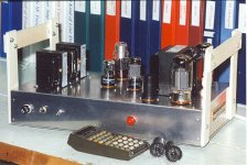
The drive voltage required is still large but boot strapping will help a lot. I did build a version of this setup for PP KT88s or PP 6550s. It makes an easy 50W + before clipping. The PS uses a pair of Hammond PTs. The OPT is a special wind from Hammond. All published in AudioXpress about 20 yrs ago.
The Gilson & Pavlat amp is a 1949 design while it looks like the Wiggins patent is 1958.🙂
The drive voltage required is still large but boot strapping will help a lot. I did build a version of this setup for PP KT88s or PP 6550s. It makes an easy 50W + before clipping. The PS uses a pair of Hammond PTs. The OPT is a special wind from Hammond. All published in AudioXpress about 20 yrs ago.
Attachments
Bootstrap Loadline Explained
Driver Bootstrapping Explained with Graphical Help
Altho this topology does appear to be positive feedback & increases stage gain slightly it does not qualify as feedback in the usual sense. Feedback over a single stage needs to go back to a cathode or grid where some gain can be realized. Back to the plate there is no gain possible.
The driver tube used in this example is a 6SN7GT, a very common hookup. The load resister is 27K powered by 400 Volts B+. So the center red line is a 27K loadline terminated on the 400 volt point on the 6SN7GT plate family of curves.
The bootstrap connexion inserts some signal into the power supply B+ in the same phase as the main signal. That results in a higher impedance loadline & more gain occurs. But the increase in gain is small, the driver is usually a triode.
The other red lines are the same slope as the 27K loadline but they terminate at the limits set by the boot strap signal. A new loadline shewn in green is the result. This loadline looks like ~42K, (500 / 11.8)K. Calculating gain for the 27K loadline & assuming rp to be 7.7K & mu of 20 the gain is 15.56. With the 42K loadline the gain becomes 16.90.
The difference is 20 log (16.90/15.56) db or 0.72 db. Not much at all! I measured the difference of gain with & without bootstrapping on my version of Norman Crowhurst's Twin Coupled Amplifier. It was ~1,5 db.
The real benefit of bootstrapping is the longer loadline available to drive the following stage. Taking the extremes of the possible signal excursions from the control grid at zero volts at one end & -20 volts at the other looks like the 27K loadline would be OK at 280 volts peak to peak. For the bootstrapped 42K loadine the same measurement looks like 318 volts peak to peak.
In a practical circuit the boot strap signal would be much larger than in this example. But the 6SN7 curves don't go to a high enough voltage to shew that here.
Attachments

Hover over the part you want to be plotted on a Watt scale and press and hold the 'alt' key, then right click and it'll generate the plot.
Thanks !
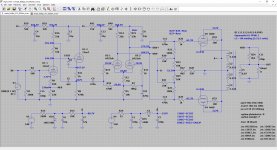
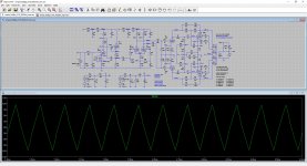
Alright, little update!
I took a different approach on trying to get the OPT in check as I already have a set of 4K Raa OPTs (Ogonowski LO-PP80-1, Polish iron, one of Europe's best) and am dead set on using those.
So I was tinkering in LTspice and it dawned on me that one way to get better control of the OPT is to put it in a local feedback loop with the KT88s. So why not simply fold the driver of the KT88 in with the OPT and the KT88. After this eureka moment I quickly realized that this must not be a new idea, and after some searching I found a similar approach used elsewhere (yes, that sinking feeling when you realize you're a dumbass after all, as someone beat you to it).
Where I'm struggling with at the moment however is to get good extension into the higher frequencies. Everything looks wonderful at 1kHz, but a 10kHz sine looks like a regular old sawtooth and I didn't even dare look at 20kHz. I've redone my compensation calcs on a fresh sheet of paper using a properly sharpened pencil and I can't seem to find anything amiss? Which usually means there's something at work here I don't (yet) understand?
Can any of you fine gentlemen (ladies?) take a peek at the attached schematic and point out what I'm missing, and possibly give me a hint on how to remedy this issue? Thanks!
Attachments
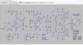
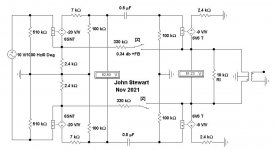
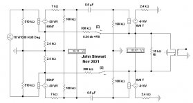
That looks like a 'Plain Jane' P-P plate driven OPT. The cathodes lead off into space, but are loaded NTL by a total of 20R cathode current sampling resistors.
Am I missing something, I don't see a PP CF Amp here at all!😀
Am I missing something, I don't see a PP CF Amp here at all!😀
That looks like a 'Plain Jane' P-P plate driven OPT. The cathodes lead off into space, but are loaded NTL by a total of 20R cathode current sampling resistors.
Am I missing something, I don't see a PP CF Amp here at all!😀
I abandoned the CF concept as it won't work with my OPTs, so this is the alternative I came up with. The drivers are in a feedback loop with the output tube and the OPT, which should help with further reducing the output impedance.
There is so much potential phase shift within that global feedback loop it's triggering my autism
There is so much potential phase shift within that global feedback loop it's triggering my autism
I know, if you squint your eyes and look a bit cross-eyed it is bearable though, I tried and it works! 😀
But yes, I may have gotten a bit overboard, welcome to hear any suggestions you might have though, I'm old, but never too old to learn.
- Home
- Amplifiers
- Tubes / Valves
- KT88 push pull cathode follower?