Hi Guys,
My first post here but long time reader.
I've recently moved to tube pre/amp and phono stages and I like the sound. I'm not an audiophile and I did it mainly as a covid project and surprisingly had great results. Build a phono stage based on Tavish vintage design and I was thinking to also build a tape head preamp to feed into a tube amp (Willsenton R8 with min 100KOhm impedance). The existing solutions are outrageously expansive and probably overkill for my setup. I'm more of a DIY kind of guy, that's why I got into R2R and tubes.
Does anybody have any experience with older tube r2r or receivers that accept tape head inputs? I understand that head inductance has to be matched with the preamp so the first question is:
- does anybody know what the inductance of the PB head of Tandberg 10XD/20TD (Ferrite) and if it would work with any of the older tube amps?
Also, I've been looking at the following amps and r2r tape head preamp section as inspiration and wondered if any of you have any experience preference on performance:
- Marantz 7 (Tape head input)
- Fisher 500C (Tape head input)
- HK A500 (Tape head input)
- Revox G37 (tape head preamp output)
- Tandberg 64x (tape head preamp output)
- Tandberg 74B (tape head preamp output - 1st stage transistor followed by 2nd and 3rd in tube)
I'm assuming the 3 receivers pre is more generic allowing a larger tape head compatibility but there isn't much info out there. The r2r pre are probably more specific to the heads used in those machines.
Any suggestions or information is greatly appreciated.
Again, I'm not looking at studio grade, just to add tubes and have good results, not worst than the r2r internal preamp.
Thanks
Using an MRL tape (19H) from Tandberg (the tape used to calibrate this deck), I get 1.3mV output at the head which means it's a low inductance head....as expected.
Do the decks/amp above expect 5mV and up, much like a phono cartridge?
Can I get away with it or do I need a step-up transformer?
Do the decks/amp above expect 5mV and up, much like a phono cartridge?
Can I get away with it or do I need a step-up transformer?
I would imagine you wouldn't need one. I made an almost all valve head amp for a cassette deck, its very lovely. Documented here:
Dave builds a valve cassette deck. - Tapeheads Tape, Audio and Music Forums
Dave builds a valve cassette deck. - Tapeheads Tape, Audio and Music Forums
Nice project, I've been playing with that idea, but I don't know enough about tape head amplification yet. Following this one.
I'm not a Tapeheads member, could you post the schematic here please?
I would imagine you wouldn't need one. I made an almost all valve head amp for a cassette deck, its very lovely. Documented here:
Dave builds a valve cassette deck. - Tapeheads Tape, Audio and Music Forums
I'm not a Tapeheads member, could you post the schematic here please?
This is the newest circuit I have easy access to. The current version I enjoy (next version) changed to schade (ecc83 anode - cathode follower cathode iirc) feedback as it is direct coupled for less complicated LF time constants and also has chrome eq switching. There is nothing special about the tubes they just need enough gain. This circuit gives a line level sort of output.

Attachments

Eq contants usually varies with tape velocity.
Yes, and with gap length and equalization standard (IEC or NAB).
Thanks for all your input guys. I also posted the same question at the tapeheads site if you’re interested in this project. It’s amazing how helpful people are.
Hbc, thanks for the schematic. Is this for a reel deck or cassette deck? Is it for iec or nab? Is th Jq a jfet? Do you know the model of j1 and c5?
Thanks again.
Hbc, thanks for the schematic. Is this for a reel deck or cassette deck? Is it for iec or nab? Is th Jq a jfet? Do you know the model of j1 and c5?
Thanks again.
Here is my tape repro project based on PCC88 tubes. It works perfect.
Beginner trying to design a hybrid tape head playback amp
Beginner trying to design a hybrid tape head playback amp
After much deliberation with the guys from tapehead I have decided to build Mikkel Simonsen tapehead schematic. Below is the link to it:
http://stiftsbogtrykkeriet.dk/~mcs/Tandberg/Tape_play_h.gif
I started building it and waiting for some parts however I just realized that my main deck (Tandberg TD20A) has IEC eq, not NAB as I expected being a North American deck. Mikkel's schematic includes only the NAB eq and was wondering if the resistors and caps values in the eq circuit could be changed to accommodate IEC eq. Below are his comments regarding the NAB eq circuit:
"The third filter creates the NAB eq (de-emphasis). It consists of the parts R13, C6, C12 and either R8+R9 or R10+R11. This filter creates a low pass that becomes active above 50Hz and "stops working" around 4kHz. The high frequency part can be adjusted by the trimmers R9 and R10. The reason there's two of them is to provide settings for two different speeds. In my case I will need 3.75 and 7.5ips. The frequency response probably won't be perfect at 3.75ips, but since I only have old tapes recorded at that speed, I don't care much about that. By making the 21kHz peak filter switchable the response could easily be made perfect though. 15ips uses the same eq as 7.5ips, so 15ips should work just fine - I don't have any decks to test that with though."
Thanks again for all your help.
Last edited:
The link doesn't work, at least not for me. Almost all modern recordings now are IEC, but if you are collecting vintage 4 track tapes produced in the U.S. or Canada you would definitely need NAB.
I designed a solid state tape amplifier a year or so ago and elected to support both at 7.5ips and 15ips. I have just a single recording with NAB EQ, the rest are IEC, but I live in 2 track land.
Have a look at the electrical design of the Studer C37 as well for inspiration.
I designed a solid state tape amplifier a year or so ago and elected to support both at 7.5ips and 15ips. I have just a single recording with NAB EQ, the rest are IEC, but I live in 2 track land.
Have a look at the electrical design of the Studer C37 as well for inspiration.

I would be tempted to make most of the frequency response inflection points adjustable, maybe even right on the front panel, especially the trims for the top two octaves. Tapes are now all very old, can be expected to have been recorded at different head azimuths, and will have aged variously. Designing for some idealized curve from almost half a century ago might prove disappointing.
I'm facing a similar issue in the upcoming year with the transfer of Paul Klipsch's tapes. Fortunately there's a guy with a basement full of old Ampex's who'll be doing a lot of the heavy lifting.
All good fortune,
Chris
I'm facing a similar issue in the upcoming year with the transfer of Paul Klipsch's tapes. Fortunately there's a guy with a basement full of old Ampex's who'll be doing a lot of the heavy lifting.
All good fortune,
Chris
Looking at the schematic, Would you be able to suggest which caps and resistors are responsible for freq response. I have basic knowledge about circuits but i’m willing to try.
Thanks
Thanks
Your circuit, in post #12, in certainly very elegant. Very nice indeed. In it, all of the EQ is done between the second and third stages, and a small resonant high frequency boost is added in the cathode of the third stage.
This boost is a rough approximation of the correction for various age-related losses, but *everything* is a rough approximation. As a first pass WAG, you could make R2 adjustable, to vary the Q of the resonance, maybe 100R linear pot. I can't hear up there any more, so can't say how important this might be.
The main EQ is done with L1, R13, and the parallel sum of C12 and C6, with the relay selectable resistors forming a stop. Again there's no DC present, so the capacitors could be switched for varying rolloff frequencies without too much drama. And the stops are already adjustable.
If this project is for your personal home entertainment, even this amount of fussing about details may not be worth the gray hair. The depth of the rabbit hole when transcribing old media is endless, but not everybody's field of interest. Some flexibility could be handy though.
All good fortune,
Chris
Thanks Chris. The information you provided is very valuable and much appreciated. Your validation of this circuit gave me encouragement. I’m still waiting for some parts and will post here my progress, impressions and hurdles.
I have finished the build and did the initial test. Initially I've tested each channel individually connected to the computer scope (I don't have a real one) to see and hear the level of background noise or hum this thing produces on its own. To my ears it sounded surprisingly very quiet. Hooked up a turntable to it since it has a 2.5mV output which is similar to the tape head and it sounded clean. Of course it has wrong eq but it did sing and quite nicely even. Quite loud, I didn't have to crank up the volume on the amp at all.
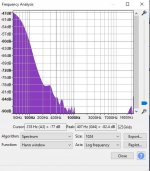
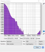
However, when I hook up both channels to the same power supply it introduces a low hum, I'd say in the 60Hz range. This hum is not audible when only one channel at the time is hooked up to the power supply. I'm attaching both spectrums, maybe you'll get an idea of the noise produced.
The power supply is a 300V @ 160mA and 6.3V @ 4.5A SMPS. I've adjusted R4, R5 and the 5K 10W resistors in order to bring the values at the plate to match the schematic......or very close to it.
Any idea why the hum when both channels are connected to the SMPS? Do I need 2 individual PS for each channel?
Thanks
Attachments
I was going to say the same thing, but truth is that you can barely find the tubes used by it and the level of building skills needed to make it work is well above average..Same thing with phono EMT JPA-66...Have a look at the electrical design of the Studer C37 as well for inspiration.
Any idea why the hum when both channels are connected to the SMPS? Do I need 2 individual PS for each channel?
We can't make specific recommendations without knowing something about the construction. God and the devil dwell together in the details. Are these on separate chassis? Is there hum with shorting plugs at the inputs? etc.
But the basic rule is to have one and only one path for each current to flow, including both power supply currents and signal currents. If you break this rule, you must go to hum jail. Re-examine your machine looking for inadverdant duplicate current paths, often in "grounding".
All good fortune,
Chris
I have shorted the inputs and it made no difference.
Everything in the build is connected to the chassis which is connected the earth ground via 3 pronged wire. The ps circuit is all connected to the same point, star config, to the chassis. Signal circuit is also connected to its own point on the same chassis. I did not connect the 2 points together as the chassis is the connection. I will try to connect the 2 points just in case.
As far as I can tell the entire circuit is connected to the chassis as the ground. Also, it doesn't matter which channel is connected. If only one of them is connected at the time there is no noise. Both channels have the same point ground.
- Home
- Amplifiers
- Tubes / Valves
- Tube tape repro head preamp for Tandberg TD20/10XD Reel to Reel