Alright, I'm clearly having a brain fart and I've probably been staring at it for too long, hence this post! 😱
I want to configure a KT88 push pull output stage as a cathode follower, see attached LTspice schematic. To the right is a conventional configuration, which obviously works fine (see plots above it) to the left the cathode follower configuration as I *think* it should be connected, but as you can see from the plots above it something doesn't work as planned. Which one of you fine gentlemen (ladies?) wants to help me out and get me on the right track?
Thanks!
Attachments

Push pull cathode followers are tricky to implement.
In a SE cathode follower there is only one tube, and it's cathode "follows" the grid. In an application where the follower is driving a transformer or other inductive load this will include a swing below ground into negative voltage. Often the driver can't keep up with this reactive swing leading to distortion.
In a push pull cathode follower when one tube is conducting hard it's cathode in pulled up to nearly the plate voltage. The transformer CT is grounded, to the other cathode is pulled down to a negative voltage equal to the conducting tube's cathode voltage. It's grid probably can't get there since it is returned to a lesser negative voltage, so the resulting grid current comes from the coupling cap by discharging it.
I have found that some sort of bootstrapping or high negative voltage supply is needed. My push pull cathode follower experiments have been sidelined for about 10 years, so I can't remember the details, but they involved bipolar supplies and HV mosfets in the driver. All were done on small tubes since things are not as messy when they blow up. I plan to experiment on this more in the future.
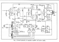
Here is a simulation showing the concept from long ago. Ignore the mosfets and zener string. They are a means of reducing dissipation in the tube and were replaced by an agile SMPS in the novel design seen in the SE cathode follower shown in this magazine article I wrote in 2007. The SE version seen in the article worked fine. I never got the push pull amp to work correctly on the bench with real parts even without the plate voltage manipulation stuff.
In a SE cathode follower there is only one tube, and it's cathode "follows" the grid. In an application where the follower is driving a transformer or other inductive load this will include a swing below ground into negative voltage. Often the driver can't keep up with this reactive swing leading to distortion.
In a push pull cathode follower when one tube is conducting hard it's cathode in pulled up to nearly the plate voltage. The transformer CT is grounded, to the other cathode is pulled down to a negative voltage equal to the conducting tube's cathode voltage. It's grid probably can't get there since it is returned to a lesser negative voltage, so the resulting grid current comes from the coupling cap by discharging it.
I have found that some sort of bootstrapping or high negative voltage supply is needed. My push pull cathode follower experiments have been sidelined for about 10 years, so I can't remember the details, but they involved bipolar supplies and HV mosfets in the driver. All were done on small tubes since things are not as messy when they blow up. I plan to experiment on this more in the future.
Here is a simulation showing the concept from long ago. Ignore the mosfets and zener string. They are a means of reducing dissipation in the tube and were replaced by an agile SMPS in the novel design seen in the SE cathode follower shown in this magazine article I wrote in 2007. The SE version seen in the article worked fine. I never got the push pull amp to work correctly on the bench with real parts even without the plate voltage manipulation stuff.
Attachments
The drive requirements are the major problem for any PP CF power amp. The driver stage problem can be solved using boot strapping as it is in the McIntosh & ElectroVoice version of the Circlotron.
One PP CF amp without boot strapping was described in Audio Magazine in the 1950s. Think it had 8X 6V6s.
One PP CF amp without boot strapping was described in Audio Magazine in the 1950s. Think it had 8X 6V6s.

Thanks jhstewart9, you’re correct, as the cathode follower has a gain <1, so the driver stage has to deliver all the voltage swing. Do you have a link for the design you refer to by any chance? It appears Google is not very helpful with digging up a schematic?
No one's answered your actual question so...Which one of you fine gentlemen (ladies?) wants to help me out and get me on the right track?
Cathode followers are non-inverting so your global NFB is actually positive feedback. Swap the DRV+ and DRV- connections.
Last edited:
Is the NFB node even connected to anything? Polarity only matters when that’s connected. I don’t see that label anywhere on the inverting or non inverting input, but part of the circuit is cut off.
That example circuit does not have global NFB, and to me looks like it’s running class A. And at sane voltages which may or may not cause the problems George describes.
That example circuit does not have global NFB, and to me looks like it’s running class A. And at sane voltages which may or may not cause the problems George describes.
It's going to the input stage, not the LTP. George's comments are secondary considerations, they wouldn't produce a square wave output.Is the NFB node even connected to anything?
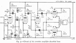
PP 6V6 X8 CF Amplifier
Ask & it will be revealed. Published in Audio Magazine May 1949. And reproduced in Audio Anthology Vol 1. There is also a link to all the original electronics magazines. I'll pass that on when I pull it up. Or someone else may have that up front.
The OPs cct runs the tubes only as triodes. With boot strapping they could be run as pentodes. That = more audio power.🙂
Thanks jhstewart9, you’re correct, as the cathode follower has a gain <1, so the driver stage has to deliver all the voltage swing. Do you have a link for the design you refer to by any chance? It appears Google is not very helpful with digging up a schematic?
Ask & it will be revealed. Published in Audio Magazine May 1949. And reproduced in Audio Anthology Vol 1. There is also a link to all the original electronics magazines. I'll pass that on when I pull it up. Or someone else may have that up front.
The OPs cct runs the tubes only as triodes. With boot strapping they could be run as pentodes. That = more audio power.🙂
Attachments
No one's answered your actual question so...
Cathode followers are non-inverting so your global NFB is actually positive feedback. Swap the DRV+ and DRV- connections.
Yes, that's the first thing I changed to no avail.
No one's answered your actual question so...
Cathode followers are non-inverting so your global NFB is actually positive feedback. Swap the DRV+ and DRV- connections.
Is the NFB node even connected to anything? Polarity only matters when that’s connected. I don’t see that label anywhere on the inverting or non inverting input, but part of the circuit is cut off.
That example circuit does not have global NFB, and to me looks like it’s running class A. And at sane voltages which may or may not cause the problems George describes.
Yes, and I tried with NFB and open loop, both to no avail.
Ask & it will be revealed. Published in Audio Magazine May 1949. And reproduced in Audio Anthology Vol 1. There is also a link to all the original electronics magazines. I'll pass that on when I pull it up. Or someone else may have that up front.
The OPs cct runs the tubes only as triodes. With boot strapping they could be run as pentodes. That = more audio power.🙂
Excellent, thank you kindly sir!
Yes, and I tried with NFB and open loop, both to no avail.
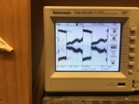
I had a K-follower driver stage doing THIS during my 200W amp development project. These are the output of one of the 12BH7s, with no output tubes installed and therefore no global feedback. Worked fine at low drive, but get it to a certain point and it broke into this (low frequency) oscillation which stayed like this till power off. I had to re-route EVERYTHING to bring the 12BH7 grids physically closer to the phase splitter output, and run grid stopper resistors directly between the sockets and the bias PCB to get it to quit doing this. Weird things happen with circuits that can develop their own negative resistance, and parasitics matter.
Attachments
Try to reduce Ig2 when in triode connected, now you have about 20mA (520*0.02=10W), Ig2 when idle is only 1.7mA.
Try to reduce Ig2 when in triode connected, now you have about 20mA (520*0.02=10W), Ig2 when idle is only 1.7mA.
I'm not entirely sure how that would result in what I'm seeing here?
Ask & it will be revealed. Published in Audio Magazine May 1949. And reproduced in Audio Anthology Vol 1. There is also a link to all the original electronics magazines. I'll pass that on when I pull it up. Or someone else may have that up front.
The OPs cct runs the tubes only as triodes. With boot strapping they could be run as pentodes. That = more audio power.🙂
This is an impressive feat of engineering, the more I look at it the more I appreciate the elegance of the design. For example the OPT is fed a negative supply voltage and the anodes of the output tubes are grounded. I think I'm going to make the effort to simulate this just to see what the designer had in mind.
Attachments

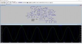
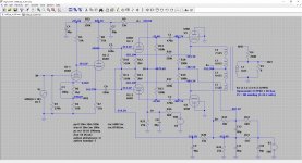
Alright, couldn't resist simulating this 1940s era design!
I made a few assumptions as the schematic was missing some vital clues. One of which are the secondary voltages on the power transformer. So I figured that if the first caps after the tube rectifiers were rated 450V, then the DC voltages across those caps were at least lower than that, so 400V seemed a good guess?
The feedback network with 100R/250R (2.5x gain), didn't make sense and didn't work in the simulation, I figured 100R/2500R (25x gain) made more sense? Regardless the amp outputs just a little shy of 2W, so I'm sure something needs further tweaking as a pair of KT88s is capable of much more, even in cathode follower configuration. One thing is clear is that the current through R18/R19 is less than a nano Ampere, hence something is probably amiss with R22/R23?
Do any of you fine gentlemen (ladies?) want to give this another go? Please find the LTspice files attached, including the libs for the 6SN7 and KT88. The simulation has all the labels for the voltages at all the nodes, so the DC operating points are all there.
Attachments
- Home
- Amplifiers
- Tubes / Valves
- KT88 push pull cathode follower?