I wonder if this Dropbox link works:

Does not look like it, so will put it as an attachment below.
Of course that worked as usual.
Now, what if I link that image? Will that work?

Did it work?
Wow! It did, how is that for a work-a-round.
I will add text later to explain it for Steve and KSTR (or anybody else interested).
Does not look like it, so will put it as an attachment below.
Of course that worked as usual.
Now, what if I link that image? Will that work?
Did it work?
Wow! It did, how is that for a work-a-round.
I will add text later to explain it for Steve and KSTR (or anybody else interested).
Attachments
Last edited:
See, one loudspeaker gets current drive, the other gets voltage drive.
In a split-load phase inverter both outputs have the same (absolute) signal voltage and the same (absolute) signal current passes through both, so impedances at both outputs are equal. Just a quibble, but these are often misunderstood.
All good fortune,
Chris
Yep! This is why this kind of phase splitter used in tube power amps, only works into very high impedances. But of course, this is basic, as we all know.
But even as a thought experiment, sorry Steve, where is the practical use of it?
But even as a thought experiment, sorry Steve, where is the practical use of it?
Sorry, that reasoning is not correct. The emitter/source side is a voltage follower and with little Early effect in place collector/drain voltage doesn't matter. Nor does load, voltage is simply impressed on it.In a split-load phase inverter both outputs have the same (absolute) signal voltage and the same (absolute) signal current passes through both, so impedances at both outputs are equal. Just a quibble, but these are often misunderstood.
The current generated in the emitter/source load (via an V-->I process along this "transfer" impedance) is reflected to the collector/drain by the circuit function of a controlled current source and therefore the collector/drain voltage is not forced to some value, only current is and this produces a voltage via the transfer impedance (I-->V process, this time) of the load.
When the collector/drain load is equal to the emitter/source load then obviously both see the same voltage and current, but termination resistance is different and thus damping in case of speaker driver loads. The collector/drain load sees no damping at all.
Just because equal loads generate equal current and voltage here this does not imply the source impedances they see are equal.
btw, the same thing happens when you replace the feedback divider of an amp with the actual loads. The bottom load is voltage driven (as forced by the feedback to make the node follow the +IN) but top load is current driven where the current is determined by the bottom load.... in fact a good test circuit to check for the subtle differences of voltage and current drive where the system transfer function still is the same for both (identical) drivers.
Last edited:
Thankyou, KSTR. You've saved me defending myself. A fine example of a phase splitter is in the John Linsley-Hood Class A amplifier below. A child of 10 can see how it works! 😀
This needs little explaining either:
Looks PLAIN WRONG to me! L2 should be 0.66mH surely, or I am not a filter designer! The 3:1 ratio of series-first BW3. 😕
For all that, I am a great believer in low-inductance and flat impedance done right. I will give an example from the real world if you are interested. Involves transformer expert Morgan Jones. 😎
Attachments
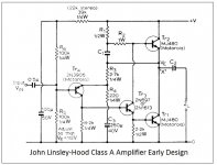
Yeah, a very tricky circuit this is.Thankyou, KSTR. You've saved me defending myself. A fine example of a phase splitter is in the John Linsley-Hood Class A amplifier below. A child of 10 can see how it works! 😀
To me, this is just a first order electric filter (L-R, assuming a resistive load, or at least low Le vs. the series L) deformed by the notch. The notch contribution is not just a notch but also often a preceding peak. It all depends on LCR parameters of the notch cells and where the tap-off point is.Looks PLAIN WRONG to me! L2 should be 0.66mH surely, or I am not a filter designer! The 3:1 ratio of series-first BW3. 😕
In my work (did some passives) this was always a good case for an optimizer (I used LSPcad), starting from educated guesses, to fit the total acoustic response to the chosen target (mag and more importantly, phase). Component values never followed any rule of thumb ratios and such.
Last edited:
I need to explain some more, I will try tomorrow. Personally, I don't do it that way anymore and I just use a single inductor and it was a long path before I made the jump. Because it seems that one inductor shouldn't be able to do the job. But it can be made to work if you got the right, but not perfect ingredients. I will use Steve's Scan-Speak with that peak as an example. It has to do with comparing on and off axis. What to take note of and what to ignore (but still taking a look).
Until 2morrow.
Until 2morrow.
Sorry, that reasoning is not correct.
When the collector/drain load is equal to the emitter/source load then obviously both see the same voltage and current, but termination resistance is different and thus damping in case of speaker driver loads. The collector/drain load sees no damping at all.
Just because equal loads generate equal current and voltage here this does not imply the source impedances they see are equal.
If your argument is that the outputs, when driven as additional inputs, react differently, then you're right, to the extent that loudspeaker loads are also sources. Equal loads are only a special case, not a general one.
All good fortune,
Chris
I'll post this because I was just running Joe's circuit up the flagpole:
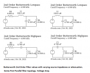
Reminding myself how ideal filters work. All straightforward enough. Butterworth is the one for flat impedance, parallel or series style. I like this stuff. People agonise over swapping one 1" 90dB tweeter for another similar one. Go on eBay for overpriced and worn out ancient exact replacements. Why? 😕
RF Tools | LC Filter Design Tool
When you start with these values in your simulator, albeit impedance corrected, you won't go far wrong. 🙂
Attachments
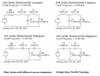
Hhm, this is only useful when it's regarded as electrical equivalents of the acoustic target functions, though I prefer to use direct form transfer function notation rather than circuit modelling with physical elements. This also more readily can account for phase impact of adjacent crossover points or roll-offs, and for time-of-flight differences, etc.When you start with these values in your simulator, albeit impedance corrected, you won't go far wrong. 🙂
But for actual speaker design those topologies and component values are almost useless as we have to factor in the drivers natural response and, to a lesser extend, it's impedance response. Therefore the actual electrical filter needed to get there is not resembling any textbook passive filter.
I sometimes use BW3 filters, and end up nearer BW5 when driver response is factored in. But that is another solution too.
I was looking at Mike Chua's Starling in the light of theoretical design:
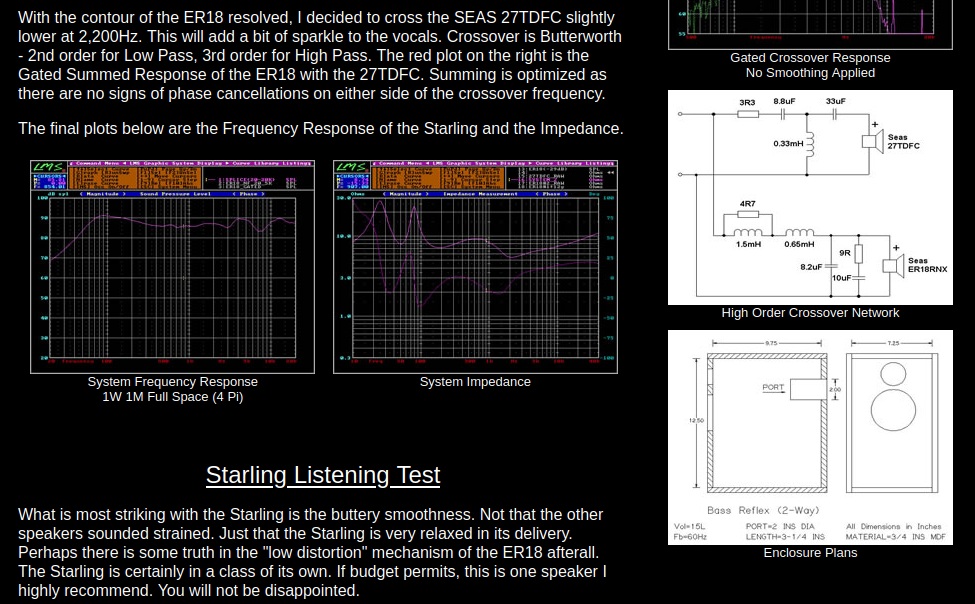
Blow me down, it's really quite close to theoretical values:
RF Tools | LC Filter Design Tool
Modify this to about 2.5kHz and mix a second order with a third order, and it's almost there:


Time alignment, bafflestep and driver selection can be played with. We know how to do this. We know how to fix asymmetric lobing. Driver selection matters, because the more you have to bend a driver, the worse impedance gets. LR4 is much more messy. Never gives flat impedance or power response. And I suppose we are looking at impedance here mostly. Might as well get it right.
I was looking at Mike Chua's Starling in the light of theoretical design:
Blow me down, it's really quite close to theoretical values:
RF Tools | LC Filter Design Tool
Modify this to about 2.5kHz and mix a second order with a third order, and it's almost there:
Time alignment, bafflestep and driver selection can be played with. We know how to do this. We know how to fix asymmetric lobing. Driver selection matters, because the more you have to bend a driver, the worse impedance gets. LR4 is much more messy. Never gives flat impedance or power response. And I suppose we are looking at impedance here mostly. Might as well get it right.
Alternatively electronic crossover and two power amps per speaker (for a two-way). Then you can do time alignment using all pass filters in the crossover.
You don't need to go that far to adjust for delays. Perhaps electronic crossovers are making people slowly forget the art of designing for custom targets, and instead going for off the shelf filters and separate delay...
Please understand the conceptual nature of the schematic. Here L1 should be viewed as a an added part to the driver, hence driver plus L1 is the driver that you now design your crossover for, which is 1st order due to L2 and the peak, assuming 5KHz, the LCR will now sort out.
But this is to me an old thought, but one that lead to a new thought, add both L1 and L2 into a single inductor, this is the better choice with a properly and carefully selected driver - then design the speaker to listen at 15 degrees of axis. Force yourself to ignore a problem is a difficult thing, but the advantages can outweigh the disadvantage.
I really need to take this slow and one step at the time and make each step stick before going on to the next point.
So let us use the example Scan-Speak driver you yourself mentioned:
[Note that I used the url address of your attachment and was able to insert into the main text - isn't that neat.]
Now in your mind interpolate where the response will be between Black full on axis and the Green 30 degree on axis. Do you see it? It will be almost flat at 15 degrees off axis.
If I see that, then in my mind, there is no need for any LCR to correct that 5-6KHz peak.
In fact, and I will get to this a bit later, you might actually be doing more damage than good.
The above driver is in fact quite excellent for our discussion because it provides the exact FR that I am looking for. I looked up the driver and the rated inductance is 0.4mH, which is not bad and yet not the best. But this no doubt is rated at 1KHz and by 10KHz this I suspect will have dropped around a third or 0.15mH.
Below are two SB Acoustics drivers that I measured the actual inductances. These are 8 Ohm examples, please note the SB17NRX is discontinued and replaced by NRX2 which is so different again (heavy cone and higher Qts). The below two are fairly close, one fibre and the other polycone.
SB17MFC: SB17NRX
1KHz 0.189mH 0.157mH
2KHz 0.101mH 0.104mH
4KHz 0.079mH 0.085mH
10KHz 0.065mH 0.068mH
15KHz 0.062mH 0.064mH
20KHz 0.060mH 0.063mH
50KHz 0.059mH 0.061mH
100KHz 0.058mH 0.060mH
Interesting that gradually above 10KHz the inductance becomes more linear, but between 1KHz and 10KHz the driver's inductance is very much nonlinear.
By using a single inductor, adjust its value so the FR is -6dB at 3KHz (which I would choose as crossover) and at 15 degrees off axis. Now design the highpass to the tweeter also to be -6dB down 15 degrees off axis (the tweeter highpass is of course another discussion).
Now the cherry on top: EQ the current and get that characteristic flat impedance, but keep in mind, what is really desirous is the flat current phase angle that accompanies it. 😉
Typically with the SB Acoustics drivers above, you end up with 0.5mH to 0.7mH range. This suppresses the nonlinear inductance very well. Your Scan-Speak example will likely need a smaller inductor value (large is good) because its starting inductance is already higher (not good). My two examples are almost SOA in this regard. I only know of one incredibly expensive driver that bests this low inductance. The lower the internal inductance allows for a larger external inductance that is by nature way more linear with frequency.
Now let us use the SB17MFC as an example using 0.5mH inductor:
1KHz 0.189mH 0.689mH
2KHz 0.101mH 0.601mH
4KHz 0.079mH 0.579mH
10KHz 0.065mH 0.565mH
15KHz 0.062mH 0.562mH
20KHz 0.060mH 0.560mH
50KHz 0.059mH 0.559mH
100KHz 0.058mH 0.558mH
That column on the right, do you see it? But the benefits are mainly in the 1KHz to 10KHz zone and you want the inductance to drop as little as possible with frequency.
Between 2KHz (close to the crossover 3KHz) and 10KHz, it is almost now flat. This is near perfect and what you want to see.
Let me know if you have followed this far and you understand the logic because, in the above example, this is the tip of the iceberg.
What you are looking at above is similar to the benefits that current-drive has and yet you are using a voltage source (remember earlier that I said there is in reality no such thing as voltage-drive, but there are voltage sources).
So Steve, let me know if you have absorbed the above?
This still does not fully explain why this trick gives us current-drive like characteristics. For that, we need to talk about distortion.
Cheers, Joe
Last edited:
When driving just a coil with a current, the voltage over the coil versus frequency goes up with 6dB/oct, however when driving this same coil with a voltage, current versus frequency will go down by 6dB/oct.
So giving your driver plus series coil a constant L and driving the combination with a voltage source means not at all that you are simulating current drive, so what it is that you may think differently.
Hans
So giving your driver plus series coil a constant L and driving the combination with a voltage source means not at all that you are simulating current drive, so what it is that you may think differently.
Hans
I agree, but...
I did not use the word 'simulate' and the cake (the making of the argument) isn't finished yet... as I made clear earlier. I did refer to 'benefits' however and that relates to what we hear. Current-drive when executed well, reduces distortion, why? And can it be done some other way? By not using current-drive and not even simulating it? That's the question.
I did not use the word 'simulate' and the cake (the making of the argument) isn't finished yet... as I made clear earlier. I did refer to 'benefits' however and that relates to what we hear. Current-drive when executed well, reduces distortion, why? And can it be done some other way? By not using current-drive and not even simulating it? That's the question.
- Home
- Member Areas
- The Lounge
- The Black Hole......