John, your welcome.
Thank you too, as your challenge has made me think about how good the faital pro 5 is and what decent efficiency you can get with a pair. In other threads people have sung its praises. I will certainly experiment with them in this kind of arrangement.")
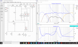
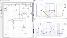
The attached screenshot show an interesting solution to improve low impedance.
Regards,
Ray.
Thank you too, as your challenge has made me think about how good the faital pro 5 is and what decent efficiency you can get with a pair. In other threads people have sung its praises. I will certainly experiment with them in this kind of arrangement.
The attached screenshot show an interesting solution to improve low impedance.
Regards,
Ray.
Attachments
Last edited:
Yes. i saw the Faithal 5FE120 only cost 20 gbp i the UK, thats a real bargain!
So strange....When i "bild up" you´r latest XSim filter with the good impedancecurve, my curve dosen´t look like your under 400 hz with the same components ???
Don´t get it......Why mine shows completely different from 400hz down!
Look at mine Frequency response curve!
Regards john
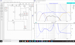
So strange....When i "bild up" you´r latest XSim filter with the good impedancecurve, my curve dosen´t look like your under 400 hz with the same components ???
Don´t get it......Why mine shows completely different from 400hz down!
Look at mine Frequency response curve!
Regards john
Attachments
Oh no, what have i done???
Its a bit like one of those pictures where you have to spot the difference.
Can I suggest reversing the bass driver phase.
Its kind of good in a way that you asked the question, as it demonstrates the importance of phase.
The number of times I have built speakers and had the phase wrong in one of the boxes. So double check everything when you start solderings and physically connecting loudspeakers.
I hope that helps.
Hahahaha....
You now, im stare so much at the "numbers" on the component´s with my bad eyesight and haven´t in my mind that you shift phase...So funny!
Don´t know why you can´t change size on circuitboard in XSim?
Have spend a few hour´s on trimming your latest filter, WITHOUT reversing the bass driver hahaha......But did some progress.
Still impedance dropps slowly after tweeter xover-point around 2,5K, and reaching 2,2 Ohm at 20K.
Big question is if i schould go for 3-4+ dB filter ( 2,3 ohm dipp at 90 hz and 2,1 ohm at 10K), or accept around 90dB filter that maby suit´s the woofer sensivity better?
regards John
Attachments
Room Gain from approximately 300Hz downwards is going to effect the graphs, so until you have tried your speakers and moved them around a bit in the room to try to balance the bass you will not know if you have too much bass or too little bass. I think one review that i saw on the internet suggested that the original my be a touch lean. A company like Jamo would have understood their reasons for voicing it that way, so maybe they were concerned about the dreaded bass boom. Also interestingly the original crossover looks very simple. You don't have one to draw up the original circuit diagram?
I would tend to err on the side of caution as too much bass is just bad news. A 5 litre bookshelf can be enjoyable for most of the time, bass is a kind of everything and nothing thing to me. I grew up with sealed designs and i find getting reflexes correct tricky.
I think there are a few more tweaks to be had and maybe going back to a second order and playing with tweeter phase and resistive pad could get you back to a flat or slightly rising impedance at 4ohms or so for the HF which would be nice.
The graph is pretty straight line I wouldn't get hung up on that too much. Your final tuning may have room ripples of 2-3 dbs bellow 1Khz, sometimes these can be left alone on other occasions a notch filter will be needed. Further each crossover can throw up its own little peak or dip that the simulation hasn't caught due to inaccuracies in the original mismeasurements
If you get a nice bass response that balances the drivers you still may want to dial back the top of the mid and keep a gentle decline through the tweeters response. If the room is full or furnishings heavy fabrics and curtains you may not have to do anything with the HF.
Even a few weeks after feeling reasonably happy with the sound you may be playing with the next value of C and the next value of R. Its really trick to get something you can listen too all day and cover the different recording quality of a music collection.
Maybe tempt your friend across for a barbecue, or at least buy him a good bottle of something for taking measurements for you.
Nearly forgot, wives and partners can have a good ear too. So you may get instant feedback.
I´m a "full-range-guy" raymondj growing up with "old" Infinity speakers, and can hardly remember ever listen to a "to-much-bass-speaker.
Of course their are some exception, with very bad bass proformance overall...Boomy and wrong.
But my speaker philosophy is, that i don´t want subwoofer´s in my main stereo-setup. ( if i don´t really have to)
So my basement speaker goes from about 22-20000 hz +-1 dB, but they are BIG!
It was my first serious diy speakerbuild and ownmade xover, and they weigh in at 210 kilo each (in 4 pices 100 liter colums) with 3x12 inch woofer in each and MTM.
These up-graded Jamo D590 going to stand in the livingroom for daily everyday use, and i can´t moved them around so much because of a windows on each side and a big tv beetween them, maby 20 centimeters sideway´s and 15 cm in the other direction
Yea, the orginal Jamo D590 i quite lean and people have to use quite small room to get help from the roomgain, and the xover look´s very simple. ( pic is from later model D590)
And non quality 8 inch orginalwoofer not give you a smile on you´r lip´s anyway.
So a few more tweaks and test, and maybe going back to a second order then
To later rajmondj
Regards John
Attachments
Hallo again rajmondj
No i have spent a cupple of hour´s adjusting 2 of our XSim xover-models.
Look´s imposseble with inverted woofer to get good responce from 150 hz down, and feels like i´ve tested everything to get netter impedance also.
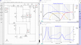
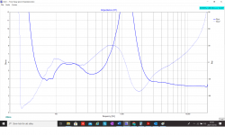
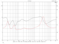
The only thing is putting a cap of 0,47 uF between possetive/+ and negative/- at the tweeter, then i get the impedance up from 2 ohm to 3 Ohm at 20K, slowly sinking from 4 ohm att xover-point 2.600 hz to 3 ohm at 20K
Notice i have the 2 dB scale on "Frequency_response curve" in my picture, think it looks nice +- 1dB
A newbie on xover-building, can you have a cap between + and - on the tweeter rajmondj ?
Regards John
No i have spent a cupple of hour´s adjusting 2 of our XSim xover-models.
Look´s imposseble with inverted woofer to get good responce from 150 hz down, and feels like i´ve tested everything to get netter impedance also.
The only thing is putting a cap of 0,47 uF between possetive/+ and negative/- at the tweeter, then i get the impedance up from 2 ohm to 3 Ohm at 20K, slowly sinking from 4 ohm att xover-point 2.600 hz to 3 ohm at 20K
Notice i have the 2 dB scale on "Frequency_response curve" in my picture, think it looks nice +- 1dB
A newbie on xover-building, can you have a cap between + and - on the tweeter rajmondj ?
Regards John
Attachments
I would be careful with just a capacitor, a capacitor and series resistor gives you some safety margin.
With a capacitor on its own as you could be asking for a very low resistance (a short) at high frequencies the resistance gives you some safety margin.
To digress some amplifiers, without a suitable network at the output of the amp did not like driving exotic low capacitance type cables. Some died.
Unfortunately the frequency graphs do not extend beyond 20Khz in the program. If one could look further out in frequency with reference to impedance you would see further swings which would help with understanding the real load impedance of a loudspeaker design beyond 40KHz and further.
As mentioned the idea of a straight line frequency response without significant bumps can be seen as an admirable challenge, but it is not a guarantee of a good sounding speaker.
You can say the crossover is designed to +/- 1 db. and if the original measurements are accurate enough, assuming the mic was a very good mike with calibration factor, and you measured them in a anechoic chamber at the design distance and then took your FRD and ZMA files you obtained and put them into Xsim you may see your predicted response curve when completed and measured in an anechoic chamber.
When measured in a room and nearby surfaces will add all sorts of frequency variations
As you move the microphone around in front of your loudspeaker in your room you will see many variations away from your +/- 1dB. The better magazine and internet based reviews of loudspeaker have room averaged results which are the results of many measurements averaged to give a better view of how the loudspeaker will sound in a room, some of these reviews also provide a power response curve to show how close designs are to the accepted gently sloping downward ideal.
Can I suggest at having a look a Vituixcad a tool that allows further refinement in designing loudspeakers via simulation.
Going back to your attached sim, without modelling how the two mid basses behave in their enclosure and how the bass behaves in its reflex enclosure we have a few unknowns that need to be considered. What do you think?
I guess we need to get a good understanding of what size the enclosure actually is for the mid basses and the woofer to help refine the design. I am guessing from 1KHz onwards the simulation may not be too far away from the sim but I doubt it is within a couple of dBs not having accurate phase information makes understanding what is actually likely to happen at the crossover frequency a unknown.
Hallo raymondj 
Yes it´s a pitty that XSim don´t show frequency graphs over 20.000 hz, 40K should be perfect!
In my case now 30-40K are valuable information if the impedance stand still at about 3 ohm´s or if it went down after 20K.
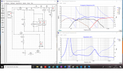
Don´t know if i understand you correct about "a capacitor and series resistor", look at my picture and tell me if i thought right.
Putting a 4,3 ohm resistor in serie after the tweeters 0,47 uF capasitor, raised the impedance with 0,2 ohm to about 3,2 ohm.
And if i look close the impedance seems to increase a little after 19.700hz, but still don´t know at 30-40K or so.
I have order a UMIK-1 for 96 euro (Yippiiii) but i don´t have a anechoic chamber, but it will take me a year to learn about measurements.
But the ears are the final judge, and you´r word earlier about be able to play all sorts of music and don´t make our ear´s wrinkle themselves after 2 hour´s playing is a must!
I have Vituixcad and use it to capture the frequency and impedance curve for making FRD and ZMA files, but learning a new program at my age (will be 55) isen´t fast-going hahaha
I will more accurate measure the mid´s and woofer enclosure when the new drivers arrive, but have them still to play music with until "the end"
And i orderd a 90° reflex-pipe so it will fit as it have to be around 32cm.
Regards John
Yes it´s a pitty that XSim don´t show frequency graphs over 20.000 hz, 40K should be perfect!
In my case now 30-40K are valuable information if the impedance stand still at about 3 ohm´s or if it went down after 20K.
Don´t know if i understand you correct about "a capacitor and series resistor", look at my picture and tell me if i thought right.
Putting a 4,3 ohm resistor in serie after the tweeters 0,47 uF capasitor, raised the impedance with 0,2 ohm to about 3,2 ohm.
And if i look close the impedance seems to increase a little after 19.700hz, but still don´t know at 30-40K or so.
I have order a UMIK-1 for 96 euro (Yippiiii) but i don´t have a anechoic chamber
, but it will take me a year to learn about measurements.But the ears are the final judge, and you´r word earlier about be able to play all sorts of music and don´t make our ear´s wrinkle themselves after 2 hour´s playing is a must!
I have Vituixcad and use it to capture the frequency and impedance curve for making FRD and ZMA files, but learning a new program at my age (will be 55) isen´t fast-going
hahahaI will more accurate measure the mid´s and woofer enclosure when the new drivers arrive, but have them still to play music with until "the end"
And i orderd a 90° reflex-pipe so it will fit as it have to be around 32cm.
Regards John
Attachments
Hmm, I thought SLS datasheet states more like 85db? Best double-check this and consider higher sensitivity 8" e.g. Scan Discovery 22W.
Also, SLS seems more suited for closed box otherwise looks to have a hump when ported. I'd recommend modelling the bass curve and port tuning from the cabinet.
Also, SLS seems more suited for closed box otherwise looks to have a hump when ported. I'd recommend modelling the bass curve and port tuning from the cabinet.
Last edited:
So you don't know how Jamo balanced their crossover to get the sound they had, and you're guessing at the baffle response? At the end of the day you're kind of starting from scratch and it comes down to who can make a better crossover, Jamo or yourself. Fortunately with the right efforts, I think it's possible.i don´t have a mic or soundcard,
Hi AllanB
Im quite new at building xover´s/speakers (as i have told i my postings), and hasen´t learn all about baffle step, step response, Energy-time-curve and so on.
Just put a lot´s of efforts in getting my Jamo D590 sounding better, nothing else.
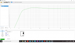
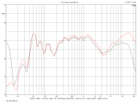
And if you look at the mesaurement from the Jamo D590 50th-Anniversary-Special-Edition in my pic´s, (from a reviews)
It dosen´t look so hard to beat that, and the orginal drivers are quite non quality driver. (But the cabinette is 26 kilo rigid)
What the mesaurments say to you ?
Still thinks only it comes down to who can make a better crossover, Jamo or myself?
And the replacement drivers im going to use are going to be superior compared to original.
Regards John
Im quite new at building xover´s/speakers (as i have told i my postings), and hasen´t learn all about baffle step, step response, Energy-time-curve and so on.
Just put a lot´s of efforts in getting my Jamo D590 sounding better, nothing else.
And if you look at the mesaurement from the Jamo D590 50th-Anniversary-Special-Edition in my pic´s, (from a reviews)
It dosen´t look so hard to beat that, and the orginal drivers are quite non quality driver. (But the cabinette is 26 kilo rigid)
What the mesaurments say to you ?
Still thinks only it comes down to who can make a better crossover, Jamo or myself?
And the replacement drivers im going to use are going to be superior compared to original.
Regards John
Attachments
Gotcha. Well check independent measurement for sensitivity here PEERLESS SLS-P830667 (Woofer 8", 8 Ohm, 180 Wmax) and Peerless' website is showing 85-86db here Peerless Drivers - Tymphany
I'd still at least compare / sim in the Scan Disco 8" - you can always stuff the port of the cabinet if you go with SLS, too and see how you like it.
Also, the Faital drivers you've picked are non-circular - were you going to route them into the cabinet for flush mount or surface mount them?
Ditto have you checked the SB tweeters will fit the cutouts?
Overall, I wonder how you came to choose each of these drivers and how you might think they are better/different from the existing Jamo drivers? Not to discourage your plans but to take a step back and be clear about the goal.
Last edited:
Not enough information.. Keep up the good work with the simulator, however if I were in your shoes I'd probably test the speakers using the original woofer crossover, because that's where the baffle information might be hidden.. then set the tweeter level, then try to fill the hole.. then back simulate what you've come up with and see if it makes sense on the screen, but also see where your ears were going with it and try to understand why it sounds as it does.What the mesaurments say to you ?
(P.S. the speaker's bass isn't like that, thats the room it was measured in.)
Thank you so much for you information motokok.
Starts to wonder why there is 3-4 different datasheets for SLS 830667 ?
It goes from 85,6 to 88dB in the informations!
If you look at the first link you sent me from dibirama, their mesaurements shows about 87,2 between 80-170 hz and i going to use it up to 150 hz. (it´s downfireing)
About the non-circular 5FE120:
I´ve have exakt 14,46 cm in the original-hole, the Faithal is 14,48 cm diagonal side and 12,45 cm on "normal sides", i hope with my carpentry skills i fix that even if i have to do modifications and routing.
The same with the tweeter the orginal hole is exakt 104 mm, and the SB26ADC is 100 mm so i can use 2 mm more to both midranges.
And because the midranges is "only" 12,45 cm, i have 2 cm margin against the tweeter i can "work with" and also the possebility to cut out some from the tweeters faceplate.
I choose each of these "new" drivers based on budjet, orginal cabinette and after reading lots of information about these drivers, especially this threads
Favorite Drivers at every price point and WHY?
SB Acoustics SB26ADC-C000-4 | HiFiCompass
Design recommendation for Peerless SLS 830677
And Swedish hifi sites
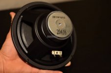
Jamo diden´t spend much on these orginal drivers, thin sheet metal basket, small magnets etc.
This is mine datasheet from Peerlees
Regards John
Starts to wonder why there is 3-4 different datasheets for SLS 830667 ?
It goes from 85,6 to 88dB in the informations!
If you look at the first link you sent me from dibirama, their mesaurements shows about 87,2 between 80-170 hz and i going to use it up to 150 hz. (it´s downfireing)
About the non-circular 5FE120:
I´ve have exakt 14,46 cm in the original-hole, the Faithal is 14,48 cm diagonal side and 12,45 cm on "normal sides", i hope with my carpentry skills i fix that even if i have to do modifications and routing.
The same with the tweeter the orginal hole is exakt 104 mm, and the SB26ADC is 100 mm so i can use 2 mm more to both midranges.
And because the midranges is "only" 12,45 cm, i have 2 cm margin against the tweeter i can "work with" and also the possebility to cut out some from the tweeters faceplate.
I choose each of these "new" drivers based on budjet, orginal cabinette and after reading lots of information about these drivers, especially this threads
Favorite Drivers at every price point and WHY?
SB Acoustics SB26ADC-C000-4 | HiFiCompass
Design recommendation for Peerless SLS 830677
And Swedish hifi sites
Jamo diden´t spend much on these orginal drivers, thin sheet metal basket, small magnets etc.
This is mine datasheet from Peerlees
Regards John
Attachments
Hallo AllanB
Ofcourse i will tryout the xover outside the speaker before i made final adjustments.
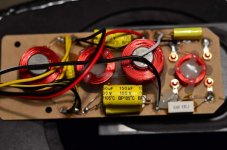
And how do you think the orginal xover and driver look´s?
Regrads John
Ofcourse i will tryout the xover outside the speaker before i made final adjustments.
And how do you think the orginal xover and driver look´s?
Regrads John
Attachments

Great, well, I think you've done your research and I will follow this thread with good hope. I can't offer much expertise but with allenb backing you up, the odds are in your favor!
My two cents is the crossover components look very cheap, with electrolytics in the main filters, and the coils are very close to each other and not oriented perpendicular from themselves in the new layout; so likely interference. You can reasonably improve on these things. Have a look Placement of coils in crossover networks
One thing I think you should address is guestimated 3-6db baffle-step losses in the lower midrange (11600/26 ~ 446hz); I'm not sure what influence downfiring the bass driver will have but generally one tries to compensate for a dip in the bafflestep region in the bass crossover so that the lost frequencies don't drop so far from the otherwise unaffected midrange such that it causes a relative peak. You can read allenb's sticky thread on the tweaking section for ideas Introduction to designing crossovers without measurement
There may be some way to model this in xsim; not sure.
That Jamo midwoofer build quality looks...uninspiring!
Last edited:
Its good to see others joining in with their help. It is all good advice and a double check of what you have done already to get to this stage.
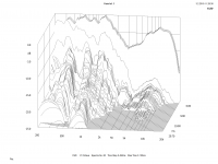
The clio data of the original frequency response is interesting, there is enough information to see what is basically going on. Its a pity nobody has the original schematic to see how the drivers were connected?
I think the low frequency dips will be linked to room modes not bad woofer mid woofer integration. The dip at 2.5Khz or thereabouts is interesting.
It could be due to wrongly connected drivers or a purposely engineered dip as even though it looks terrible it can still sound good, or the ear doesn't seem to mind this.
Or that it it is the result of the simple crossover? Pure conjecture on my part.
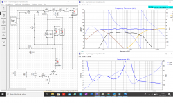
Just for fun while we wait for some measurements. I have guessed some small baffle step profile, played with the the impedance and driver phase. It acted as a diversion from a bad day at work.
Again i stress a guestimate until we have better data which will probably change everything.
The clio data of the original frequency response is interesting, there is enough information to see what is basically going on. Its a pity nobody has the original schematic to see how the drivers were connected?
I think the low frequency dips will be linked to room modes not bad woofer mid woofer integration. The dip at 2.5Khz or thereabouts is interesting.
It could be due to wrongly connected drivers or a purposely engineered dip as even though it looks terrible it can still sound good, or the ear doesn't seem to mind this.
Or that it it is the result of the simple crossover? Pure conjecture on my part.
Just for fun while we wait for some measurements. I have guessed some small baffle step profile, played with the the impedance and driver phase. It acted as a diversion from a bad day at work.
Again i stress a guestimate until we have better data which will probably change everything.
Attachments
- Home
- Loudspeakers
- Multi-Way
- 3 way upgrading Jamo D590 replacements and filter question