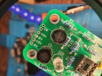
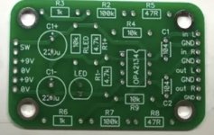
Is the power supply (the pads on the board) configured to allow either 9v or 18 volt operation?---(i think its only set up for 9v)
There are only two 'switch' pads which suggest single rail virtual ground to me.
Questions.
1/ Does pin 4 go to the lower left 0V pad? Yes or no.(pin 4 looks to go to the my right 0v)
2/ Do the middle two of that group of four power pads join together? Yes or no. (no)
3/ If the above was 'Yes' then do those two pads connect directly to any other point on the board? Yes or no? NA
4/ Does the left hand +9v pad (the one next to the switch pad) connect to that switch pad? Yes or no. (+9V CONNECTS TO SWITCH PAD)
5/ If 'yes' above then does the other (left hand) switch pad connect to pin 8? Yes or no. (yes)
If the answers are yes, yes, no, yes and yes then it is single rail, virtual ground and it can operate on 9 or 18 volts. For 9 volts you would use the two outer power pads only. The switch pads would need linking (or via a switch).
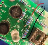
This is the power inputs, sorry a bit messy now, the plastic just melted.
Sack whoever did the screen printing 🙄😱
Jeez Louise
Attachments

I'm starting to think its not coming back, Mooly I've done most of the tests with the multi-meter, no power seems to be on the pins it needs to be at. And the places that should read 0 have a micro-V reading?
I might just build my own with the PCB boards I have LOL be easier at this rate.
I might just build my own with the PCB boards I have LOL be easier at this rate.
It will only draw about 0.015A even with a power hungry 5532 fitted.
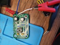
Do what I show in post #67 and see if it all works.
Do what I show in post #67 and see if it all works.


That looks OK but you need to securely tag the wires, otherwise you will get all sorts of intermittent readings. That white wire also looks to be nearly touching the resistor next to it.
Does the LED light up?
Does the LED light up?
How can you not be seeing voltage at the devices pins? This is as simple as it gets. You've got pin 8 connected directly to SW and then to +ve of the first battery.
Then pin 4 connects directly to the -ve terminal of the second battery.
Unless some of the traces were completely burnt out this doesn't make any sense.
If you set your multimeter to test continuity (the one where it beeps if you touch the red and black probes together) what does it show if you test between SW and pin 8 and then the other 0V and pin 4? It should beep between both.
Images of this
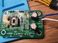
If the LED is not lighting when you connect power directly to the two 4.7k resistors: Is the LED in backwards?
From looking at the PCB it seems that there must either be no power applied or that the LED is in backwards.
Last edited:
I would agree the printing is a bit misleading.
Also the first post does kind of read as though it did all work until the NE5532 was swapped for an OPA2134 (LOL)
Also the first post does kind of read as though it did all work until the NE5532 was swapped for an OPA2134 (LOL)
I don't think so. I'll take LED out and pit another in to check.
Just connect the supply as I showed and measure across pins 8 and 4. You absolutely MUST see 9 volts doing that.
The LED only shows power is present, it won't stop it working... unless no power really is the cause 😉
- Home
- Design & Build
- Parts
- Upgrade's didn't work, fake OPA2134?