I have come up with a design for a push pull el84 amp.
I must admit some bits were pinched from other peoples designs.
The el84 has 220R cathode resistors which are bypassed.
This should give about 30mA through the valve with no input signal.
Does this mean my reversed mains transformer being used as an output transformer will have DC through it with no signal ? IS this a problem ?
I am assuming the 30mA goes up and down with input signal.
Does this mean each half of the push pull is really working in class A ?
If they are matched tubes and individually biased, the DC should cancel well enough.
It will be in class A, until it isn't.
It will be in class A, until it isn't.
Cathode-resistor biased amps can't get far past class A without de-biasing and sounding bad. EL84 is almost universally worked class A up to 90+% of nominal maximum power, and sold as "That Great Class A Sound!!!" (like 'Class A' cigarettes).
BTW: I just learned (after 60+ years of hanging with smoke) that "class A" is a US tax category, NOT a quality.
Yes, DC flows in OT. In push-pull, it tends to cancel. If tubes are somewhat balanced, plain E-I cores can usually stand the residual DC.
BTW: I just learned (after 60+ years of hanging with smoke) that "class A" is a US tax category, NOT a quality.
Yes, DC flows in OT. In push-pull, it tends to cancel. If tubes are somewhat balanced, plain E-I cores can usually stand the residual DC.
Attachments

Could a circloton not help self balance out the DC with the complication of floating supplies?
They work fine OTL style, so a transformer should be the same?
They work fine OTL style, so a transformer should be the same?
If they are matched tubes and individually biased, the DC should cancel well enough.
It will be in class A, until it isn't.
I want to add my comment to this answer quoted.
The cancellation is the cancellation of magnetic flux happening in the output transformer.
Even a small mismatch generally is not an issue for EI transformer.
You sure?Cathode-resistor biased amps can't get far past class A without de-biasing and sounding bad. EL84 is almost universally worked class A up to 90+% of nominal maximum power,
Philips themselves
https://pdf1.alldatasheet.es/datasheet-pdf/view/95279/PHILIPS/EL84.htm
state various operation modes, in Class A , AB and even B (with fixed bias).
On page 4 they state:
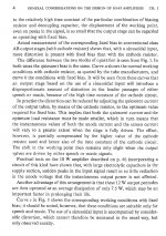
Operating characteristics Class AB
Va______250V_________300V
Rk______130 ohm___ (so cathode biased)
Vi (drive) 0__8_________0 __10 Veff (RMS)
Ia______31__37.5 mA__36__46 mA (so Class A it´s not)
Wo _____0___11 W____0__17 W
Dtot 3%______________4%
An increase of only 10 mA between zero signal and clipping indicates to me that it stays in class A for most of its power range. Maybe not 90%, but well over half for sure.
In this thread there are some screenshot of the signal at the cathode of EL84 on a push pull with fixed bias, pentode connection
EL84PP, a simply circuit
About the mismatch of the power tubes in some case even a little dc current residual produce a magnetization
Walter
EL84PP, a simply circuit
About the mismatch of the power tubes in some case even a little dc current residual produce a magnetization
Walter
Some transformers take DC imbalance better than others. In some applications a couple extra percent distortion doesn’t matter, or may even be desirable. When and if it matters, you want well matched tubes and carefully adjusted bias.
Well, that´s the definition of Class A-B 🙂An increase of only 10 mA between zero signal and clipping indicates to me that it stays in class A for most of its power range. Maybe not 90%, but well over half for sure.
Not bad for *crude* cathode resistor biasing.
Bet fixed bias would work WAY better, but hey! It´s 1946!!!!
(Psst!!!! , don´t tell him it´s 2021 😉 )
😛
Last edited:
But if you’re playing it at two watts, it will be operating class A. Maybe as much as 10 watts if biased high enough. It’s only class AB if you’re driving it with enough signal to cause one tube’s current to actually reach zero.
Fixed bias amplifiers *can* be operated at a lower Q point than cathode biased for a given distortion level. That doesn’t mean they have to be. If it is, it will leave class A sooner.
Fixed bias amplifiers *can* be operated at a lower Q point than cathode biased for a given distortion level. That doesn’t mean they have to be. If it is, it will leave class A sooner.
wg_ski,
I think that for an output stage (SE or Push Pull) that uses a fixed B+ voltage:
Fixed Bias does not reduce the plate to cathode voltage.
But Self Bias does reduce the plate to cathode voltage (B+ Volts - Self Bias Volts).
I believe that might be the cause of lower distortion at a given power output using fixed bias, versus using self bias.
So, for the self bias amp, increase the B+ voltage by the amount equal to the Self Bias voltage.
Now compare that to the fixed bias amp.
Of course you will get different results with self bias if you do extended time sine wave testing, the bypass caps will charge up to a new voltage, and the bias will shift.
Just do the test with a tone burst.
Music transients are often like tone bursts.
Yes, I admit the Organ enthusiasts with a 32 foot pipe 'pounding' all the way through side one of an LP, might be disappointed with a self bias amp.
Last edited:
For self bias the negative bias is changing dynamically with the current ( power ) on the cathode resistor , you can't just add some B+ volts to be like a fixed bias 😀 This is how it is ... 2 different ways for biasing a tube .
Obviously because of this the self bias needs higher idle current , if you want power , and also it is not possible to achieve the same power as for fixed bias .
Obviously because of this the self bias needs higher idle current , if you want power , and also it is not possible to achieve the same power as for fixed bias .
Last edited:
...but hey! It´s 1946!!!!...
No EL84 in 1946.

36mA to 46mA is not 10mA but 28%. Curvature (AKA rectification in RCA lit) can easily be 20%. The other 8% is because Philips assigned classes by popularity not by school-book definitions. (Also a few Philips suggestions are industrial, motor-drivers with constant signal and amplitude.)
FWIW, many P-P EL84 amps run 110 Rk. I can't tell if this is different from Nigel's plan.
Let's debate something *meaningful*. How many angels dance on your pins?
You know I know that. 😉No EL84 in 1946.
It was said half for comedic purpose and half to remark it´s crude outdated Technology 🙂
1946 is as good as any other "REAL Old School" date 🙂
So crude indeed tha Cathode "bypass" capacitor actually integrates cathode current and bias is shifting all the time, in an unpredictable way.
Talk about "crude" 😱
That.36mA to 46mA is not 10mA but 28%.
Ok, how about starting a new thread discussing "Class AB is not REALLY Class AB but Class A in disguise"Let's debate something *meaningful*. How many angels dance on your pins?
Won´t get as lively/boring as others I won´t mention but maybe could reach 50-100 posts?
There´s already 2 starters, an earlier answer and yours here:
Philips assigned classes by popularity not by school-book definitions.
Mmmmhhhh, guess the dancing angels might be less controversial. 🙂
Last edited:
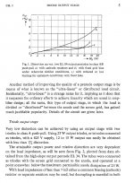
About the differences in distortion between class AB with cathode resistor and class AB without cathode resistor, see attachments.
The use of the designations "class A" and "class AB" sometimes looks a bit arbitrary. In this datasheet for the EL82 there is data for class A push-pull operation but the anode currents do rise with higher power levels.
https://frank.pocnet.net/sheets/030/e/EL82.pdf
The use of the designations "class A" and "class AB" sometimes looks a bit arbitrary. In this datasheet for the EL82 there is data for class A push-pull operation but the anode currents do rise with higher power levels.
https://frank.pocnet.net/sheets/030/e/EL82.pdf
Attachments

So crude indeed tha Cathode "bypass" capacitor actually integrates cathode current and bias is shifting all the time, in an unpredictable way.
Talk about "crude" 😱
That is very good point and I'd not even considered that.
I know from studying DSD modulators using valves and opamp DSD modulators, the use of a capacitor as an integrator. However I'd not considered the cathode bypass cap would do the same thing. Feedback yes, integration no.
Also, initially I just copied them as others had them in schematics. However, now I tend just to not bother purely from what I have seen in LTSpice - if I need more gain I'll use a different tube or add a stage. Then again I've seen people state amps without a cathode bypass cap as "bad sounding" and "unlively" however from the sims I can see there's additional current spikes flowing supplied by the cap as the voltage swings and then replenished. Perhaps from a speed perspective there's something but everything's a compromise right?
Last edited:
Weather statistics graphs, are often done as Integrators.
They can take hours, days, weeks, months, or years to see any change.
The same goes for self bias bypass cap integration.
How long of a time period do you want to make it integrate?
It is all math and uF or milli Farad, or more, etc.
They can take hours, days, weeks, months, or years to see any change.
The same goes for self bias bypass cap integration.
How long of a time period do you want to make it integrate?
It is all math and uF or milli Farad, or more, etc.
Last edited:
But if you’re playing it at two watts, it will be operating class A. Maybe as much as 10 watts if biased high enough. It’s only class AB if you’re driving it with enough signal to cause one tube’s current to actually reach zero.
Fixed bias amplifiers *can* be operated at a lower Q point than cathode biased for a given distortion level. That doesn’t mean they have to be. If it is, it will leave class A sooner.
Errr...that is an AB amp. There is no Class A in an AB amp. This heaping steamer of an idea that an AB amp has 'class A power' for some fraction of its useful output is a claim invented in a Marketing department( where they are quite familiar with big steamers ).
cheers,
Douglas
In the class AB there is a portion of the signal where the circuit is in class A , proportioned with the bias current and,of course , with the load.
The bias current in AB, for each power tube is not 0 mA
Otherwise is class B, near the cutoff
My opinion on bias
I think in the past the cathode bias was used because is easy, cheaper ( compare with fixed, one more coil, one diode bridge, one cap, one resistor,one cap, one trimmer) and it is safe mainly when the tube operate at full class A.
With a little flutuaction of voltage the cathode bias it is safe for tube
But there is not reason to use the fixed bias when perfectly involved; in any type of circuit.
I never seen the "blockade" of the tube when it is oveloaded ( close to desruptuin)
Walter
- Home
- Amplifiers
- Tubes / Valves
- Valve push pull theory.