Depending on how you have to connect your inductors to the PCBs, I would consider placing them at equal distances both from each other and from signal wiring, while at the same time not having them close to the back panel. The wires will have some ripple on them, and also the inductors can have a magnetic? field affecting circuitry and signal wires etc. also, bridges should be kept close to center of chassis, and equally far away from signal wiring etc.
As for the the runcaps, I would keep those. Think about Mightys layout. Main difference to yours being inductors: how about putting the inductors under the PSU PCBs? Wiring will be short, place will not be an issue. Inductors are easier to place in a P2P PSU, since with a PCB you need the inductors on the sides of the PCB, or you will need to extend their wires.
I am putting my bridges between the transformers, saving space and keeping them far away. Excited to hear what Mighty thinks. I most like the last one you said looked good up there in the earlier post, of the ones posted.
Edit: that is the same one ZM liked best. Go for it!
Two further questions:
GND cables from thermistors go tho the same earth screw from VDE?

Snubbers on bridges are simple ceramic caps or R+Cs?

GND cables from thermistors go tho the same earth screw from VDE?
Snubbers on bridges are simple ceramic caps or R+Cs?
Thanks, o Mighty!
@Andy PCBs are smaller than chokes
improvise
long 3mm spacers, additional metal plate for pcb if needed
etc.
Two further questions:
GND cables from thermistors go tho the same earth screw from VDE?
View attachment 983815
Snubbers on bridges are simple ceramic caps or R+Cs?
View attachment 983816
one screw near IEC is for all chassis connections ......... in your case 3
snubbers - if you have Quasimodo, do it
if you don't have Quasimodo, skip them
Last edited by a moderator:
Those snubbers are infact R+C’s, if my eyes serve me right. If you look really close at the yellow shrink, they are a tiny bit thicker on one side. Mightys mighty solder skills at work.
If I were you, I’d go for suggested solution, and extend inductor wires for furthest rails if needed (solder only). If the amp is quiet, be happy. If not, you can consider inductors under PCBs. That will move bridges and the whole PSU a bit further away from the circuit, and possibly enabling you to twist some of the inductor wires together.
If I were you, I’d go for suggested solution, and extend inductor wires for furthest rails if needed (solder only). If the amp is quiet, be happy. If not, you can consider inductors under PCBs. That will move bridges and the whole PSU a bit further away from the circuit, and possibly enabling you to twist some of the inductor wires together.
Thanks, o Mighty!
@Andy PCBs are smaller than chokes
improvise
long 3mm spacers, additional metal plate for pcb if needed
Once chokes arrive, I'll try this way:


Very nice, Mightys CRC gone CLC without major layout changes.
I am testing layout right now, details, bridges to be more exact. Long ground planes from machine shop will be made soon, freebies, and that sorta lays the ground for the rest of the layout.
@Mighty: How close is too close between J Zen PCBs and bridges? Ie, would you say Peppeninos bridges are far enough away not to inflict noise in the circuit?
Regards,
Andy
best scenario is that amp pcbs are in Music Room, while bridges best to situate near the river

I am thinking about putting the PSU in the cellar. But jokes aside: inside the chassis, millimeters and centimeters have an effect. Any rule of thumb here?
keep them as far from cchannel boards, twist all AC wires, twist all DC wires
all that - as far as you eager to bother with
in my builds you can see that I wasn't so OCD
same applies for Papas FW builds........you can learn much just looking at FW originals .........
all that - as far as you eager to bother with
in my builds you can see that I wasn't so OCD
same applies for Papas FW builds........you can learn much just looking at FW originals .........
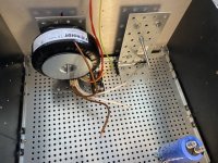
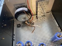
I know you have limited twisting OCD, compared to some. Papa does too, ref to FW builds. However his bridges are always put at the back of the chassis. I think I am OK/good either way, but the two pics attached show two alternatives. Practically speaking, one bridge on each side of the tranny, is preferred, if distance to PCB is OK. Distance to first MOSFET measured to approx 7 cm.
The other solution, between trannies, is obviously the quietest, having all the worst ripple carrying wiring in one place as far away from sensitive stuff as possible, approx 20cm. But space is a bit tight.i could easily make it work though, and also there is room to move the trannies further from each other.
Why this challenge? Many, many caps. A proper BJ needs big caps So no space for bridges in front of trannies.
The other solution, between trannies, is obviously the quietest, having all the worst ripple carrying wiring in one place as far away from sensitive stuff as possible, approx 20cm. But space is a bit tight.i could easily make it work though, and also there is room to move the trannies further from each other.
Why this challenge? Many, many caps. A proper BJ needs big caps
So no space for bridges in front of trannies.Attachments
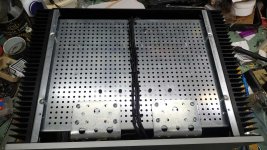
move your donuts all the way to front
that way you'll gain few cm, then put bridges in front
you can also mount L brackets for Donuts from underside, there is enough space from base plate to front plate
that way you'll gain few cm, then put bridges in front
you can also mount L brackets for Donuts from underside, there is enough space from base plate to front plate
Attachments
Last edited:
Softstarts behind them is reason why they aren’t all the way against the front… will contemplate… bridges placement is the compromise, or loose 100.000uF 🙁
Perfect solution would be your NTC board between trannies, and suggested mounting from under the bottom plate. You sending? I did order a blank PCB to make NTC board myself. It sid not have cooper in it, so not usable for mye purpose… Greenhorn.
Edit 2: Haha! Funny. That is just the solution I have been making in my head, needing your NTC board since connection block is unwanted. But every time I ask about PSU parts you dodge my question
Is the problem I never sent you that Viking shield I promised?
Last edited:
move your donuts all the way to front
that way you'll gain few cm, then put bridges in front
you can also mount L brackets for Donuts from underside, there is enough space from base plate to front plate
Fuuuuugly! 😎
.......
Is the problem I never sent you that Viking shield I promised?
ok, zip that shield and put it in e-mail
write what you want
obviously I skipped that question (about pcbs) being overwhelmed with other more important issues you had
besides Viking OCD, I mean
@BenE123
FWIW I drive a pair of 1028BE with one ACA at times and it works fine for me. Not sure how they compare to the Aria 948 on paper.
The Aleph J would have roughly the same output into 4 ohms as an ACA? Yes?
I’ll be building an Aleph J next…okay not next, but the one after that.
I have 1028 too. Aleph J did not have any problems to drive them very loud in a big room. However, M2X is a better match and way better sounding combo with those loudspeaker.
move your donuts all the way to front
that way you'll gain few cm, then put bridges in front
you can also mount L brackets for Donuts from underside, there is enough space from base plate to front plate
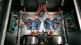
Mighty ZM, I see speaker protection circuit, or am I wrong - again? That builder or buyer being sissy, or is it maybe a very good idea? Didn’t use one on my BA-3. then again, if I can get DC on the outputs if, say, a JFET blows, maybe I should consider putting a condom on the outputs. Or will the caps in the circuit rid of it?
Last edited:
- Home
- Amplifiers
- Pass Labs
- Aleph J illustrated build guide