D
Deleted member 148505
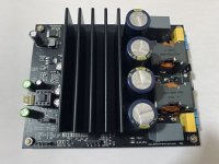
I'm currently improving my JLE interface (similar functionality to pete millet's interface but without the RMS voltmeter)
My interface prototype uses INA1651 and OPA1656 and I'm currently using it to measure my Sylph-D200.
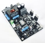
First pic Motu M4 loopback (SE)
Second pic Motu M4 + JLE Interface loopback (SE).
Slight loss on the output signal (due to input impedance). Only slight degradation on THD+N!
Problem is that the results are good because the input and output diode protections are removed, If I put them back, the loopback THD+N will become worse (+6dB). So I'm currently looking for input and output protection methods.
Motu M4 uses TPD2E007 for each terminals, i will look for similar methods.
I went with putting a low signal relay that will disengage the output terminal on a certain (adjustable) preset Vrms output (to protect the soundcard / audio interface like Motu M4). And another relay for adding a voltage divider on the input. Then TPD2E007 for INA1651's ESD protection.
D
Deleted member 148505
New Products in 2nd week of September
TICore400M : Mono RTR TPA3255, with PFFB jumper headers, OPA1656, high quality o/p inductors. Price will be around 90USD shipped.
Tectonic-D500 : 500W mini "small profile" RTR class-d amplifier for plate-amp replacement / retrofit. Compatible with most plate amps!
Product updates:
New JLE Interface partial board: Soundcard "manual ranger" with pre-soldered INA1651, ultralow-noise supply (TPS7A4901 / TPS7A3001), and all SMT parts, up to 90Vrms floating input, balanced output, and isolated usb power.
New Softstart circuit partial board : pre assembled SMT parts, uses 110V-220V onboard switching supply.
D
Deleted member 148505
Attachments

D
Deleted member 148505
What is the D500 based on...or would you rather not say?
Will it work at 50v?
Would rather not mention but it is based on irs2092. It can work with +/-50V with a resistor change. I've worked on countless IRS2092 designs and it is the culmination of it.
If you need an amp with 50V single supply then TICORE400M is good. It can output clean 400W at 2 ohms.
D
Deleted member 148505
Latest batch of ATS heatsink now has smoother and shinier contact pads. I can run sine wave tests on TICore400M at full power (400W 2 ohm) for longer time without triggering over temp protection. Previous batch can be polished too with high grit sandpaper (3000 or more) and liquid polish for better performance.
Attachments
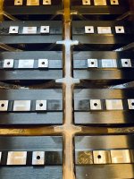
With thermal compound, you don't need a very smooth contact interface (300-400 grit is an arguable "knee" for diminishing returns), but the thermal transfer is always improved with flatter surfaces.
If one has a small surface plate (9"x12" is a common hobby size for small metrology and/or flattening purposes) it's a pretty trivial task to flatten surfaces of small parts.
EDIT: If the center "pad" is recessed, and all 3 "pads" need to contact at the same time, it's not possible to properly flatten all 3 surfaces on that heatsink on a surface plate without some pretty complicated setup.
Last edited:
D
Deleted member 148505
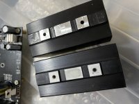
Previous batches actually do have some rough surface, it looks like it has some sealant to avoid corrosion, ormight be a mild aluminum corrosion. I thought the surface was normal.
I'm just shocked with the thermal improvement on these new batches. It can really hold long sine wave tests without triggering the thermals (provided that there's an active air cooling).
If you have the previous batch (before the shortage happened) I think there's no complications if you'll be using high grit polish, I think it will not 'eat' the gap between the IC and the pad that much.
With thermal compound, you don't need a very smooth contact interface (300-400 grit is an arguable "knee" for diminishing returns), but the thermal transfer is always improved with flatter surfaces.
If one has a small surface plate (9"x12" is a common hobby size for small metrology and/or flattening purposes) it's a pretty trivial task to flatten surfaces of small parts.
EDIT: If the center "pad" is recessed, and all 3 "pads" need to contact at the same time, it's not possible to properly flatten all 3 surfaces on that heatsink on a surface plate without some pretty complicated setup.
Attachments
Last edited by a moderator:
D
Deleted member 148505
D
Deleted member 148505
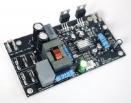
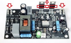
Any heatsinking required for the TO220s?
The TO-220 mosfets need to be mounted on the heatsink, although at idle only small amount of heat is dissipated, I can touch the mosfets indefinitely.
Attached screw mounting holes.
Attachments
Hey there.
I am new and am excited to get this running.
It is an ideal starter for me.
TICore260BTL PFFB V1A
I have all the components and psu.
I have been reading through the thread and although it is interesting, it is taking me a long time 🙂
I know I want to leave it pffb.
I will be going SE and know to change the solder jumpers.
(Until I work out about balanced 🙂 )
Then I need to make the slight adjustment (wish me luck) is the following still the current advice?
I thought I saw something about another option somewhere.
Also, it is just for higher power levels is it?
Also, is there anything else I need to know before I get to it please? :
D
Deleted member 148505
Hey there.
I am new and am excited to get this running.
It is an ideal starter for me.
TICore260BTL PFFB V1A
I have all the components and psu.
I have been reading through the thread and although it is interesting, it is taking me a long time 🙂
I know I want to leave it pffb.
I will be going SE and know to change the solder jumpers.
(Until I work out about balanced 🙂 )
Then I need to make the slight adjustment (wish me luck) is the following still the current advice?
I thought I saw something about another option somewhere.
Also, it is just for higher power levels is it?
Also, is there anything else I need to know before I get to it please? :
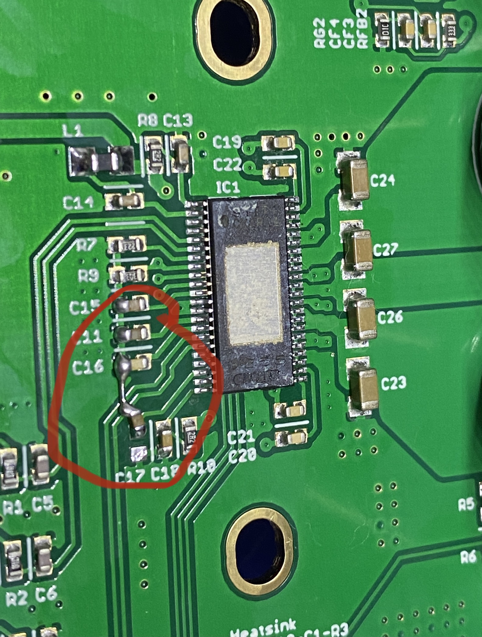
Yes you need to do the mod in your attached picture. On versions V1A/V1B, I added the series resistors for GVDD supply just like in the TPA3255 datasheet, but unfortunately, the sound was degraded and grounding for VBG was affected. So it requires the said modification.
You need to make sure that the following resistors are 0 ohm (or shorted out)
- RA7, RA6 (opamp supply)
- R8, R10 (GVDD supply)
Also for me, 600kHz osc frequency sounds better. (you need to disable PFFB or change PFFB values if you change the osc frequency). For 600kHz osc freq, you can change the output filter caps to 680nF 15mm pitch poly cap, it will result to a flatter 8ohm frequency response.
---------------------
Generally, do not mess with the opamp supply and/or GVDD supply in any TPA3255 builds. (For Sylph-D200 users, make sure that C11 and C16 caps for GVDD supply are unpopulated)
Putting cap on AVDD improves the highs / treble. (not available in TICore260BTL). With this cap added, PFFB mode is not needed to improve the highs. I use Panasonic FC 100uF in my latest Sylph-D200 / Sylph-D400 shipments.
---------------------
Regards,
Lester
[FONT=FreeSans, sans-serif]Great, thanks.
Ummmm
Can I ask the values of the C17 capacitor please?
I broke mine. It went fine the first time, then I tried to improve it. Doh.[/FONT]
[FONT=FreeSans, sans-serif]Also, can I ask some noob questions please?[/FONT][FONT=FreeSans, sans-serif]
I think I saw a startup guide, but I can’t find the link now.
Is there one?[/FONT][FONT=FreeSans, sans-serif]
I seem to have bought the wrong [/FONT][FONT=FreeSans, sans-serif]SOIC-8 [/FONT][FONT=FreeSans, sans-serif]to[/FONT][FONT=FreeSans, sans-serif] DIP-8 SMT [/FONT][FONT=FreeSans, sans-serif]adapter.
[/FONT][FONT=FreeSans, sans-serif]The pins are too thick to push into the socket.[/FONT][FONT=FreeSans, sans-serif]
Blocked
[/FONT][FONT=FreeSans, sans-serif]Could you point me in the right direction for the right one?[/FONT]
[FONT=FreeSans, sans-serif]For the 680nF 15mm poly caps, [/FONT][FONT=FreeSans, sans-serif]are they metallised poly?
Does it matter how good they are? What tolerance? [/FONT][FONT=FreeSans, sans-serif]
“Also for me, 600kHz osc frequency sounds better.”
Well, then I am keen to have a go. :[/FONT][FONT=FreeSans, sans-serif])[/FONT][FONT=FreeSans, sans-serif]
[/FONT][FONT=FreeSans, sans-serif]But, sorry, I don’t understand the words.[/FONT][FONT=FreeSans, sans-serif]
So, I need to replace the grey ones on the board for 680nF 15mm pitch poly cap.
[/FONT][FONT=FreeSans, sans-serif]Is that what changes things to 600kHz?
[/FONT][FONT=FreeSans, sans-serif]How do I change PFFB values?[/FONT][FONT=FreeSans, sans-serif]
[/FONT][FONT=FreeSans, sans-serif]Do I disable PFFB or not?[/FONT][FONT=FreeSans, sans-serif]
[/FONT][FONT=FreeSans, sans-serif]Sorry, could you please spell out what I have to do?[/FONT]
[FONT=FreeSans, sans-serif]
[/FONT]
[FONT=FreeSans, sans-serif]Thanks[/FONT]
D
Deleted member 148505
- C17 is 1uF 0603
- No more startup guide since it was not updated ever since.
- You can search LCSC with this part no. MH254V-11-08-1196 or MH254V-11-40-1196. It has dimensions on the datasheet. Though just by looking at the picture, I think the pins are still thick.
- I think just do the shorting out of RA7, RA6 (opamp supply) and R8, R10 (GVDD supply) first. Then you can proceed with other mods afterwards.
Regards,
Lester
[FONT=FreeSans, sans-serif]Great, thanks.
Ummmm
Can I ask the values of the C17 capacitor please?
I broke mine. It went fine the first time, then I tried to improve it. Doh.[/FONT]
[FONT=FreeSans, sans-serif]Also, can I ask some noob questions please?[/FONT][FONT=FreeSans, sans-serif]
I think I saw a startup guide, but I can’t find the link now.
Is there one?[/FONT][FONT=FreeSans, sans-serif]
I seem to have bought the wrong [/FONT][FONT=FreeSans, sans-serif]SOIC-8 [/FONT][FONT=FreeSans, sans-serif]to[/FONT][FONT=FreeSans, sans-serif] DIP-8 SMT [/FONT][FONT=FreeSans, sans-serif]adapter.
[/FONT][FONT=FreeSans, sans-serif]The pins are too thick to push into the socket.[/FONT][FONT=FreeSans, sans-serif]
Blocked
[/FONT][FONT=FreeSans, sans-serif]Could you point me in the right direction for the right one?[/FONT]
[FONT=FreeSans, sans-serif]For the 680nF 15mm poly caps, [/FONT][FONT=FreeSans, sans-serif]are they metallised poly?
Does it matter how good they are? What tolerance? [/FONT][FONT=FreeSans, sans-serif]
“Also for me, 600kHz osc frequency sounds better.”
Well, then I am keen to have a go. :[/FONT][FONT=FreeSans, sans-serif])[/FONT][FONT=FreeSans, sans-serif]
[/FONT][FONT=FreeSans, sans-serif]But, sorry, I don’t understand the words.[/FONT][FONT=FreeSans, sans-serif]
So, I need to replace the grey ones on the board for 680nF 15mm pitch poly cap.
[/FONT][FONT=FreeSans, sans-serif]Is that what changes things to 600kHz?
[/FONT][FONT=FreeSans, sans-serif]How do I change PFFB values?[/FONT][FONT=FreeSans, sans-serif]
[/FONT][FONT=FreeSans, sans-serif]Do I disable PFFB or not?[/FONT][FONT=FreeSans, sans-serif]
[/FONT][FONT=FreeSans, sans-serif]Sorry, could you please spell out what I have to do?[/FONT]
[FONT=FreeSans, sans-serif]
[/FONT]
[FONT=FreeSans, sans-serif]Thanks[/FONT]
Grarea. I'd follow Lester's advice and just do the R and C mods for now as they are simple but require steady hand soldering. Magnification even from mobile phone camera afterwards to check your work is a good idea.
You need adaptors with round pins, not the cut square section. I may have some spare to send you
You need adaptors with round pins, not the cut square section. I may have some spare to send you
Thanks jimk04. The round pin makes way more sense.
I didn't think to look at the pins when i ordered.
Quite why I thought I could do a solder bridge of that length when I have never tried before, I don't know 🙂
I was going to put a bit of wire, but then thought I would copy the photo. Again, Doh!
1) smd cap. C17 is 1uF 0603. don't I need to know the voltage and tolerance for it as well?
2) As I am putting in an order for that, I might as well get the bits for the upgrade, right? All I need is the poly caps isn't it?
680nF 15mm pitch poly cap. Don't I need the voltage for this as well?
R60II36805030K | KEMET 0.68μF Polyester Capacitor PET 160 V ac, 250 V dc +-10%, Through Hole | RS Components
Thanks.
D
Deleted member 148505
Thanks jimk04. The round pin makes way more sense.
I didn't think to look at the pins when i ordered.
Quite why I thought I could do a solder bridge of that length when I have never tried before, I don't know 🙂
I was going to put a bit of wire, but then thought I would copy the photo. Again, Doh!
1) smd cap. C17 is 1uF 0603. don't I need to know the voltage and tolerance for it as well?
2) As I am putting in an order for that, I might as well get the bits for the upgrade, right? All I need is the poly caps isn't it?
680nF 15mm pitch poly cap. Don't I need the voltage for this as well?
R60II36805030K | KEMET 0.68μF Polyester Capacitor PET 160 V ac, 250 V dc +-10%, Through Hole | RS Components
Thanks.
For C17, get 25V or higher. You can also use 100nF for the meantime (same as EVM) if you want to make it work right away
For poly caps, get 100VAC or higher.
You also need 10K ohms 0603 for changing the osc freq.
Regards,
Lester
- Status
- Not open for further replies.
- Home
- Vendor's Bazaar
- Amplifier Modules and PCBs For Sale