I have been given a broken JAM turntable which has a USB/digital output. The main board is basically kaputt but the motor, speed selector switch circuit and transformer/power-in circuit seem to be working ok so I want to convert it to just a simple analogue-only record player.
The motor is a 9V/12V pretty much like this one...New 13s/lot DC9~12V MOTOR with all switchs and wires 33 1/3, 45, 78RPM / turntable gramophone Plattenspieler|switch shell|motor figuremotor sliders - AliExpress
but the transformer and power board (bridge rectifier and filter cap) puts out 20VDC (previously it supplied the main board which then fed the motor with the required voltage (12VDC).
So basically I was thinking I could use a 12V zener diode to regulate the voltage to 12V to then supply the motor. Would a circuit like this work (call it 'circuit A')...?
https://www.electronics-tutorials.ws/diode/diode_7.html
(first pic on this page)
I was thinking if I get a 5w 12V zener then it would have a max current of around 410mA so the series resistor would have to be around 20ohms if Vin is 20V. Can it be that simple or am I missing something?
Another circuit I was looking at (call it 'circuit B')) was this one ... 12 Volt Regulated power supply circuit using zener diode ... which specifies motors in the description. I'd have to change some of the values here as this is 15V to 12V. Also I don't know what the transistor is for in this one...?
Any thoughts gratefully received...
Tom.
At full motor load (65mA) the Zener still must have at least 10% (or more) of its rated current ( 410mA x 0.1 = 41mA)
to stay in regulation. So use a resistor of (20V-12V) / (41mA + 65mA) = 75 ohms, 0.8W. (Use a 2W resistor.)
Then under open circuit the Zener would have ( 41mA+65mA ) = 105mA and 1.2W dissipation.
That's ok, or you could raise it to half rated power, 2.5W.
Then 2.5W /12V = 208mA. So the resistor would be 8V /208mA = 39 ohms, 1.7W. So use a 3W resistor.
Then when the motor draws 65mA, the Zener would still have 143mA left, which is plenty.
But the second circuit is better, since the Zener does not have to work so hard, and you don't have
to worry about it dropping out much, just verify the operation at low AC line (105VAC). The Zener current
would stay about constant in this circuit, since the transistor's base current is very small by comparison.
Last edited:
Thanks so much Rayma for the thorough answer and calculations. I have a couple of sollow up questions if you have time...
1. If I went for the second circuit would I need to change the values of resistors and caps as the source voltage off the transformer/recifier is 20V not 15V?
2. Do I need to get that exact transistor or is it a certain category of transistor and anything close will work?
3. What do you mean by 'just verify the operation at low AC line'? [btw I am in uk so AC is 230VAC)
Thanks again!
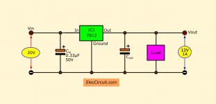
I would use a 7812 instead of the zener... It's not much different in cost and it'll just work better.
That looks nice and easy - and cheap! What value would I need for the second cap in the diagram? Also would I need to attach a heat sink?
Thanks for your help!
I would use a little screw on heat sink.
I use these: XSD | XSD C108928 | Heat Sinks - LCSC.COM
22uF should be alright for the cap. No bigger than 100uF I'd say.
Koda
I use these: XSD | XSD C108928 | Heat Sinks - LCSC.COM
22uF should be alright for the cap. No bigger than 100uF I'd say.
Koda
I would use a little screw on heat sink.
I use these: XSD | XSD C108928 | Heat Sinks - LCSC.COM
22uF should be alright for the cap. No bigger than 100uF I'd say.
Koda
Brilliant - many thanks. Is 0.33uF correct for the first cap (in the diagram)? Or should that be 33uF? So 33uF and then 22uF?
- Home
- Source & Line
- Analogue Source
- Can I use a simple zener circuit to step down voltage for a turntable motor?