Hello from a full range virgin 😀
I will outline my plan. I want to build a sealed enclosure for this little 5.3 full ranger that will be high passed with a first order filter incorporated in the input stage of my power amp (passive line level).
I want to use this with a 6.5" mid bass which is in a TL enclosure already kindly built and designed for me by B&W 🙂 I will just remove the tweeter and drastically reduce the low pass filter. The low pass for the 6.5" mid bass will be at 500 Hz which is roughly the middle of the baffle step. The high pass for the 5.3 will be a first order at 500Hz and also done passively at line level in the input stage of my power amplifier.
Can you kind people please suggest a sealed cabinet volume for the 5.3 ? I obviously know it's VAS and Qts already but I am unsure how an ideal volume would be changed by high passing it at 500Hz.
I want to put it in a sphere or B&W style tear drop and put it on top of the B&W cabinet and set back a little to time align it with the 6.5" woofer.
Many thanks
Last edited:
It isn't really changed, since you're well above the mass-corner frequency. Assuming a voltage source amplifier, light lagging and about 1/2ohm series R for wire, connections etc., about 2.6 litres once the driver is accounted for will put you on a maximally flat Butterworth. Since you're only using 1st order slopes, I'd be inclined to avoid a peaking (Qtc > 0.707) alignment.
Thankyou for your reply Scott. You answered my question perfectly 🙂
Another related question if I may.
What is the maximum distance I can get away with between the centre of the 6.5" bass driver and the centre of the 5.3 at 500Hz xover and first order filters ?
Many thanks
Another related question if I may.
What is the maximum distance I can get away with between the centre of the 6.5" bass driver and the centre of the 5.3 at 500Hz xover and first order filters ?
Many thanks
In an ideal world, you'd have the centre-to-centre distance at no more than about 1/3 wavelength of the crossover frequency so it acts as a virtual point source, so 9in [nearly], although if you can get it tighter, so much the better. Since we don't live in an ideal world and other factors can come into play, 'as close as you can manage' is the general message.
Thanks again Scott. The way things stand the closest I can manage is 10 inch. A rethink is required. Trying to use the TL cabs with 6.5 incher in is causing a problem as the top edge of the driver is 11cm from the top of the enclosure because the tweeter is above it.
I was going to remove the tweeter and block the hole up.The 6.5" kevlar mid bass was crossed over with a single series inductor at 3,5kHz by B&W. I think this is too high and causing some nasties to be audible. Reducing the xover frequency to 500Hz seemed a good idea for that reason.
As I can't design a xover for toffee then the alpair 5.3 on top was a prospective solution. Obviously I can't use any of the TL enclosure volume for the 5.3 as the tuning will all go to pot. My only other option is to move the mid bass up to the top of the baffle to reduce rge distance to the 5.3 plonked on top. But I can't see that ending well either.
These are unstuffed volumes. They can shrink a bit with damping (which is highly suggested).
Given the high XO i would tend towards a bit more volume.
Scott suggested ⅓ wavelength, Danley’s work says ¼ is nore appropriate. At these distances the drivers essentially become coincident, ie they are in time, and the fist order XO will not disturb that.
I tend to start XO at about 0.707 x BS(-3)
dave
Attachments
P4 speakers?
Yes, P4 from the late1990's. My main speakers for 20 years.

These are unstuffed volumes. They can shrink a bit with damping (which is highly suggested).
Given the high XO i would tend towards a bit more volume.
Scott suggested ⅓ wavelength, Danley’s work says ¼ is nore appropriate. At these distances the drivers essentially become coincident, ie they are in time, and the fist order XO will not disturb that.
I tend to start XO at about 0.707 x BS(-3)
dave
Thanks for your reply Dave.
The options I have are
1)move the 6.5" to top of baffle
2)decrease the xover frequency but it won't correspond with the baffle step
3)forget about this project
You can always drop a 4" piece of PVC behind the tweeter hole. You can leave it sealed or run it ou tthe back and damp it as a midTL. Easier than building a separte box, and that should get teh drivers well withing 350-400 Hz quarter-wave. You are trying for about 7” centre-to-centre.
Moving the woofer would change the Zd.
WOn’t look as slick as the teardrop thou.]
dave
Moving the woofer would change the Zd.
WOn’t look as slick as the teardrop thou.]
dave
These are unstuffed volumes. They can shrink a bit with damping (which is highly suggested).
Given the high XO i would tend towards a bit more volume.
Scott suggested ⅓ wavelength, Danley’s work says ¼ is nore appropriate. At these distances the drivers essentially become coincident, ie they are in time, and the fist order XO will not disturb that.
I tend to start XO at about 0.707 x BS(-3)
dave
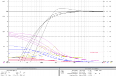
Maybe I am a bit thick here but I can't work out what enclosure volumes those four black FR curves correspond with 🙁
Lowest Q reaches the lowest but is well damped. The one with the bump is Q = 1. Max flat (0.707) and the slightly more damped bessel (0.58).
So if you go across the bottom of the chart the Qs go up a notch with each line. There is a continuum of alignments and you usually stay between the min & max in the chart.
These voumes are undamped, adding damping lowers the Q (effectively increasing the volume) a bit.
dave
So if you go across the bottom of the chart the Qs go up a notch with each line. There is a continuum of alignments and you usually stay between the min & max in the chart.
These voumes are undamped, adding damping lowers the Q (effectively increasing the volume) a bit.
dave
Thankyou Dave, much appreciated.
I am going to have a play with it myself in winisd.
Is there anything to be gained by going aperiodic ? Apart from lower volume for a given alignment that is.
I am going to have a play with it myself in winisd.
Is there anything to be gained by going aperiodic ? Apart from lower volume for a given alignment that is.
You can always drop a 4" piece of PVC behind the tweeter hole. You can leave it sealed or run it ou tthe back and damp it as a midTL. Easier than building a separte box, and that should get teh drivers well withing 350-400 Hz quarter-wave. You are trying for about 7” centre-to-centre.
Moving the woofer would change the Zd.
WOn’t look as slick as the teardrop thou.]
dave
Well I have just enough room to mount the 5.3 above the mid bass. Doing it that way would be much easier than adding a 2.6L teardrop on top but as you say, nowhere near as cool and not as good for diffraction.
As regards putting a 4" pipe behind the (enlarged) tweeter cut out for the 5.3 - I had considered that but that will reduce the box volume for the 6.5" TL. Surely that can't be good ? What would the effect be ?
The pipe will notsignificantly impact the TL. i have done it more than a few times.
dave
Cool. Thanks Dave. I love it when a plan comes together 😀
110mm drainage pipe has 102mm internal diameter. Internal depth of the cab is 196mm. Volume of the pipe will be 1.6 litres minus volume of Alpair 5.3 (don't know what that is). Some stuffing will make it seem a little larger. Not 2.6L as Scott suggested up thread.
I haven't decided if i should cut a hole in the back panel or not. I guess that will take some experimentation with stuffing.
Pity I can't time align the 5.3 with the 6,5' mid bass which has quite a deep cone. Angling the cab back might help a bit but there is only so far you can go with that.
Buy the time you properly chamfer the back of the A5 cutout/rebate you have created just about exactly the same volume the part of the driver that sticks in the box. I did the drawings and math for a number of drivers and at least for the smaller ones, it ends up like that.
The volume is a bit small. Take a ⅜” drill and put a bunch of holes in the bac of the box to make the midTweeter box leaky. Then fully damp such that the stuff just behind the driver is low density. Then density increases as you approach the rear of the tube. I’d see if i could find some open cel foam and put it right over the holes on the inside.
If you want to go beyond tuning by ear GM’s clik-test (i have to do a drawing) or by measuring the impedance and working towards the most suppressed resonant peak.
Remember the ¼ wavelength is a sphere not a line. The different depths make little to no difference at the frequencies involved given the proximity of the drivers. They are essentially coincident. Something a coax won’t usually do without somesort of time delay in the XO.
dave
Buy the time you properly chamfer the back of the A5 cutout/rebate you have created just about exactly the same volume the part of the driver that sticks in the box. I did the drawings and math for a number of drivers and at least for the smaller ones, it ends up like that.
The volume is a bit small. Take a ⅜” drill and put a bunch of holes in the bac of the box to make the midTweeter box leaky. Then fully damp such that the stuff just behind the driver is low density. Then density increases as you approach the rear of the tube. I’d see if i could find some open cel foam and put it right over the holes on the inside.
If you want to go beyond tuning by ear GM’s clik-test (i have to do a drawing) or by measuring the impedance and working towards the most suppressed resonant peak.
Remember the ¼ wavelength is a sphere not a line. The different depths make little to no difference at the frequencies involved given the proximity of the drivers. They are essentially coincident. Something a coax won’t usually do without somesort of time delay in the XO.
dave
Thanks again Dave

I have some open cell foam but will have to get some loose fibre stuffing as I don't have any.
I will not worry about the time alignment then 🙂
I am thinking about other ways to do this. Thought about sticking a black acrylic 200mm diameter hemisphere on the top of the speaker and cutting a hole through into that. Join the driver and the acrylic hemisphere with a 45 degree bend.
I assume Zd is concerned with having the driver being a certain distance from the end of the line. That is set in stone then unfortunately.
I assume Zd is concerned with having the driver being a certain distance from the end of the line.
Exactly. A key spec in an ML-TL.
dave
Exactly. A key spec in an ML-TL.
dave
Hello Dave.
How about this crazy idea. Mount the mid bass up firing on the top, run an internal 6" pipe down from the top panel and terminate it at the same distance from the top as the centre of the mid bass used to be when front mounted. Would that preserve the Zd ? There would still be a stub and the 6.5" would still appear to be the same distance from the end of the line. At 500Hz xover would the pipe cause any nasty resonances. 6" internal pipe diameter and 7.5" length.
That would enable me to put a forward firing alpair 5.3 in a 20cm sphere right above the up firing bass driver.
Probably a crazy idea ? (I like up firing drivers very much)
- Home
- Loudspeakers
- Full Range
- Sealed enclosure for Alpair 5.3