That's a good point. I actually have Crown XLS1000s I've used for years in various sub applications. But I want to develop an all-diy system and the HB would be good for that. I'm using the 1000s right now to power the LX-Minis. The first time I've used them for anything but subs. I'm quite impressed with their sound actually. But yes, HB is overkill. I do have a 650HP Corvette that I rarely use to its full extent. Maybe I have that overkill trend going.
to bullitt5084
Hello Bob,
although it is 'off-topic' - I thought about a dark green fastback when I read your name first time...🙄
Now it is a beasty Corvette....😉
Cheers
Dirk 😀
Hello Bob,
although it is 'off-topic' - I thought about a dark green fastback when I read your name first time...🙄
Now it is a beasty Corvette....😉
Cheers
Dirk 😀
You are on point actually. I have a 2001 Bullitt edition mustang track car modified to run 8sec quarter miles. But I also have C7 Z06 Corvette for a street car.
Drilled it out, filed the edges, added some touch-up paint to keep it from rusting. All good now.
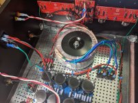
Beyond all hopes and expectations... it works. No problem at all Biasing it to 3.5 and 0 offset. The only hick-up is I used the same grounding scheme 6L6 demonstrated at the beginning of this thread and I also used that one with my F6 with great results. But on this build it was noisy. I circled back to the scheme Nelson suggested in his article and problem solved. It's very quiet now.
IF no-one looks at the attached pictures and posts they see something I did stupid, I'll take it off the test speakers and put it in the system with the LXMini's with it's little F5 brother tonight.
Thanks again for all the assistance folks!!

IF no-one looks at the attached pictures and posts they see something I did stupid, I'll take it off the test speakers and put it in the system with the LXMini's with it's little F5 brother tonight.
Thanks again for all the assistance folks!!
Attachments
to bullitt5094 #1285
Hello bullitt5094,
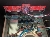
the only thing I see is that your thermistors are touching the blank metal washers
on your Mosfets. As long as the colourcoating on the thermistors doesn't crack - no problem.
I bent my thermistors touching the plasticbody of the Mosfet. No chance for short
to ground. 😉
Cheers
Dirk 😀
p.s.: Enjoy the sound - F5T is a fantastic poweramp


Hello bullitt5094,
the only thing I see is that your thermistors are touching the blank metal washers
on your Mosfets. As long as the colourcoating on the thermistors doesn't crack - no problem.
I bent my thermistors touching the plasticbody of the Mosfet. No chance for short
to ground. 😉
Cheers
Dirk 😀
p.s.: Enjoy the sound - F5T is a fantastic poweramp
Thanks Dirk. Good suggestion. I'll do that and also modify the F5 since it's the same way on it.
The F5T v2 has some hours on it and sounds great in my LXMini application. Using the F5 for highs and the F5T for the mids is more power than the Minis can handle, which was a concern.
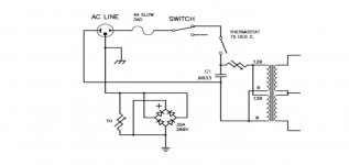
But on the picky side, the amp is still generating some hum. You can't hear it from the seated position in my very quiet listening environment, but my F5 is dead quiet. I'm wondering why the Turbo isn't. Can anyone offer suggestions specific to this Amp and build I could try before I just start experimenting randomly? Or is some hum from this topography normal? Below is the grounding scheme I used.

But on the picky side, the amp is still generating some hum. You can't hear it from the seated position in my very quiet listening environment, but my F5 is dead quiet. I'm wondering why the Turbo isn't. Can anyone offer suggestions specific to this Amp and build I could try before I just start experimenting randomly? Or is some hum from this topography normal? Below is the grounding scheme I used.
Attachments
Last edited:
Do you notice any difference between the hum from two channels? I'm asking
because your transformer is closer to one side.
because your transformer is closer to one side.
Good observation but no difference in channels. I looked at that too. My F5 is arranged exactly the same way with zero problems.
Another point is, my F5 used the grounding scheme 6L6 showed at the front of this thread. It was VERY noisy. I changed to the scheme shown in Nelson's concept article using the diode block and it was a significant improvement. Don't know if that's a clue or not. I had another noisy component in the system that I thought was causing everything, but I got that dead silent and what remains comes from the Turbo. Same with/without inputs attached. And the other component is dead silent when attached to the F5 so I assume it's OK now.
And Dennis, thanks for your help on this. You've been very responsive to my rookie inquires. I really appreciate that!
I have the Bias at close to 350mv for the higher of the two measurements on each channel output board with zero offset, or real close to it. It's been very stable. The hottest temperature on my heat sinks is only 110F after being on for hours with the cover in place. It feels barely warm. Do I have enough bias dialed in?
I believe you are not using the diodes in parallel with the source resistors. If that's true, you can go over 350mV without fear, so long as the temps at the heatsinks and transistors aren't too high.
You heatsink temp is pretty good and it seems you have a bit of room.
If you want to experiment, you can bump the bias up a bit and see if you notice an improvement. I would try keeping the max heatsink temp below 50C (122F) though.
You heatsink temp is pretty good and it seems you have a bit of room.
If you want to experiment, you can bump the bias up a bit and see if you notice an improvement. I would try keeping the max heatsink temp below 50C (122F) though.
Thanks Dennis. And I did not install the diodes but inverted the Output cards to keep the transistors at the bottom of the heat sink as suggested.
My F5 is only at 105F. Should I bump that up too? As I understand it additional bias allows more output wattage and less distortion. Too much bias causes smoke and fire. I'll be real careful not to get into the fire zone!!!
My F5 is only at 105F. Should I bump that up too? As I understand it additional bias allows more output wattage and less distortion. Too much bias causes smoke and fire. I'll be real careful not to get into the fire zone!!!
What is the ambient temperature of your listening room?
What bias/current level are you running your F5 at, and at what rail voltage?
If you are using the standing +/-23V rails and 1.3A (0.6V across 0.47 ohm resistors)
you are running about 30W dissipation per output mosfet. With the IRFP240/9240,
to maintain a good safety margin for longevity I wouldn't have them dissipate
much more power than that.
Increasing the bias generally lowers the distortion, and can give more power into class A
at lower impedances.
I don't think I biased it that high. I'll check it. I just found one article with this "But with the 4U's heatsinks, the amplifier's temperature stabilizes at just about 20 degrees Centigrade above ambient room temperature."
Mine is a standard build with the U4 chassis. With my room somewhere around 70F, +20c would mean almost 140F. I'll check the bias and not clutter up this thread off-subject. Thanks again Dennis.
Mine is a standard build with the U4 chassis. With my room somewhere around 70F, +20c would mean almost 140F. I'll check the bias and not clutter up this thread off-subject. Thanks again Dennis.
Actually I don't think it's toasty enough! I put a meter on the F5 just now and it's only at 525. I think I biased it low during the initial set-up thinking I'd go back later and get it to 6 but never did. I'll tweak it up closer to 6 and see how it acts.
What would be the typical transformer for a balanced F5t v3 mono block (or a v2 stereo) running in pure class A on 24vac secondaries? Around 800VA?
Last edited:
- Home
- Amplifiers
- Pass Labs
- F5Turbo Illustrated Build Guide