Hi Klaus,
Thanks for your interest in testing the principle.
The source code for the proof-of-concept is in GitHub - pavhofman/nonlinear-compensation: Compensation of nonlinear sound card distortions for audio measurements . The latest commits for the static-distortion compensation will be pushed to the repo soon, I have to clean them up first to remove hard-coded parameters.
As of the OS I would recommend upgrading to ubuntu 20.04 which already has Octave 5.1 in the repos (the version I code for). 3GB RAM is not much for the OS + java/REW but I guess it should do.
While theoretically the software supports calibration adapters ranging from fully manual to completely automated (relays + steppers), I do not test and bugfix the less-automated versions when making changes. In fact I do not have any manually-operated adapter anymore as operating one is tedious and error-prone.
The automated adapter (pictured in my posts) requires a 3D-printed stepper/pot holder, two rather expensive multiturn pots ( 534-5K VISHAY 10-Speed Rotary Potentiometer 5KΩ Precision-Wire Poti Linear +- 0,25% 2W | eBay ), Leonardo Pro (chinese clone), OPA1622 for the output buffer, OPA1656 for the input isolation, 2x DRV777, 6 signal relays. I have several spare PCBs left from the minimum 5pcs JLCPCB order.
Last edited:
OK, thanks!
I'll upgrade octave to 5.1 (or even just upgrade to 20.04LTS) and clone your repo and see what I'll get going ;-)
Also I will scan through this whole thread to collect details so I can come up with meaningful non-trivial questions. Same about the hardware you made, I'll have to lookup and study it (I'm not clear about what exactly it does right now). Then, if it makes sense I'll gladly buy a blank PCB, well appreciated.
The balanced/SE adapter provides two selectable calibration paths:
1) a fixed balanced/SE LP filter
2) a balanced voltage divider with each branch finely tunable, or two SE tunable dividers
Also, the adapter grounds output lines selectively to allow measuring signal level in each balanced branch and adjusting the voltage divider in respective branch to the same level. SE operation does not require the grounding relays - the previous version of the adapter.
To allow attaching a DUT, a relay at input of the input buffer selects between DUT output and the calibration paths. This adapter version does not have a relay disconnecting DUT input from the adapter/soundcard output - not required for the experiments.
Not really related to distortion compensation, but a compensation too, just extremely sensitive - electromagnets compensating motion of 40kg mirrors of the LIGO gravitational waves detector down to less than one thousandth the size of proton, reaching basically quantum standstill (corresponding to temperature of 77 nanokelvins) Physicists bring human-scale object to near standstill, reaching a quantum state: The results open possibilities for studying gravity's effects on relatively large objects in quantum states -- ScienceDaily
Now that is the truly amazing technology.
Now that is the truly amazing technology.
Last edited:
I wonder how those physicists deal with the motion of the Earth; when the mirrors stand still with respect to the Earth, they are still rotating every day, unless they are on the North or South pole.
vovi: very nice results, the MOD3 analog card connected to the digital EMU1010PCI? How were the level and phases of the DAC distortions compensations obtained, by successive approximation?
MarcelvdG: IIUC what matters is the position of the mirrors relative to the laser and detectors. Knowing position of the whole assembly at the detection time just allows to determine direction towards the GW source, to some extent.
phofman: The MOD 3.0 analog card is connected to the new US3 usb card. Adjustable Harmonic Phase Generator - Best spec ADC Chip currently.... ?? | Page 15 | Audio Science Review (ASR) Forum
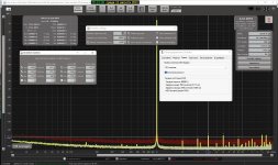
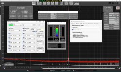
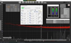
for statistics: REW beta13b  RTA + E.Sokol ©generator with harmonics & phases @ CS4398 + AK5394 = The MOD 3.0 analog card is connected to the new UX3 usb card
REW @ genSokol @ MOD3 - YouTube
RTA + E.Sokol ©generator with harmonics & phases @ CS4398 + AK5394 = The MOD 3.0 analog card is connected to the new UX3 usb cardREW @ genSokol @ MOD3 - YouTube
An externally hosted image should be here but it was not working when we last tested it.
Do I understand correctly that you took the loopback distortions as measured by REW, scaled their amplitudes for the DAC signal level, inverted the phases and added them to the generator?
That would be joint-sides distortions compensated on the DAC side. The joint-sides-compensated DAC outputs reversed ADC distortions now, to be nullified on the ADC side.
Or the same can be done on the ADC side, with a bit of DSP before REW. The goal is to compensate the DAC-side distortions in the generator and the ADC-side distortions in the DSP before the analyzer software... which requires splitting the joint-sides distortions to respective vector contributions of each side.
phofman, I see the only one practical reason of DAC-ADC pair compensation, it makes it possible to measure a DUT amp inserted inside of the pair, however. on the same frequency and exactly the same input voltage. To me, much more sense in the ADC compensating, as ESS does that with LUT(DACs as well).
I have not been able to find inner workings of the ESS compensation. From what I seen it is frequency and level specific https://cdn.shopify.com/s/files/1/0321/7609/files/DAC3_-_2nd_Harmonic_Compensation.GIF?v=1478880997 . Just like a simple polynomial compensation https://www.diyaudio.com/forums/equ...nsation-measurement-setup-40.html#post6532409 https://www.diyaudio.com/forums/equ...nsation-measurement-setup-40.html#post6536105 https://www.diyaudio.com/forums/equ...nsation-measurement-setup-40.html#post6532409 . Therefore I assume the ESS H2 compensation value adjusts second order term and H3 some third order term of a polynomial with which the ESS chips multiply sample values before DAC/after ADC conversion. Especially when the C2 value affects both H2 and H3 (typical effect of polynomials).
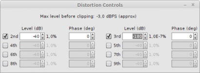
The level/phase compensation of specific harmonics as discussed in most of this thread is for fine-tuning, at specific level and frequency, of distortions left after the wide-band/wide-level polynomial compensation. Of course it requires fast automated calibration at the current frequency and level, stepped-sine/level instead of continuous sweeps, and co-operation with the measurement software. The sweeps cannot give very precise results anyway RTA Window :
I find the simple polynomial compensation with automated measuring/calibrating the polynom coeffs the very basic feature of a measurement device. However it requires a bit of DSP either in the measurement PC (nobody wants to maintain DSP-equipped drivers) or in the actual device (mostly dumb USB-UAC2 FPGAs are used which are difficult to program DSP like this).
Therefore my undergoing project uses a 4-core CPU running streamlined linux in the USB analyzer, presenting already processed and cleaned-up UAC2 stream to the USB host running the measurement software (REW in particular).
The level/phase compensation of specific harmonics as discussed in most of this thread is for fine-tuning, at specific level and frequency, of distortions left after the wide-band/wide-level polynomial compensation. Of course it requires fast automated calibration at the current frequency and level, stepped-sine/level instead of continuous sweeps, and co-operation with the measurement software. The sweeps cannot give very precise results anyway RTA Window :
Although much, much slower than a log sweep the stepped sine measurement captures N (noise and non-harmonic distortion) and THD+N (neither is available with a log sweep) and can measure low distortion levels more accurately than a sweep, particularly at high frequencies and for higher harmonics. This makes it well suited to measuring the distortion of electronic components.
I find the simple polynomial compensation with automated measuring/calibrating the polynom coeffs the very basic feature of a measurement device. However it requires a bit of DSP either in the measurement PC (nobody wants to maintain DSP-equipped drivers) or in the actual device (mostly dumb USB-UAC2 FPGAs are used which are difficult to program DSP like this).
Therefore my undergoing project uses a 4-core CPU running streamlined linux in the USB analyzer, presenting already processed and cleaned-up UAC2 stream to the USB host running the measurement software (REW in particular).
Last edited:
yes, this is exactly the total THD compensation of the ADC and DACphofman:correctly that you took the loopback distortions as measured by REW, scaled their amplitudes for the DAC signal level, inverted the phases and added them to the generator
- Home
- Design & Build
- Equipment & Tools
- Digital Distortion Compensation for Measurement Setup