Hi im restoring a old blewup PPI 2300M
and i got a problem with the power supply maybe it isnt the power supply
It had some 25N05N blown on 1 Channel
it still has the original Resistors 460 ohms and 2.2k ohms i checked them all and they are on tolerance
the other channel is ok with all the older semicounductors but the drivers because i was having DC voltage on the pads of the audio output on both channels (MPSU06 and MPSU56)
i had to put them backwards and twist the legs of pins 1 and 2 to match the old drivers
DC on Audio Output pads solved.
so i was having problems on the power supply waveform
the top was a little waved so i finished changing capacitors
Changed the ones with the mpsa056 on top of the ic sg3525a
and got it fixed
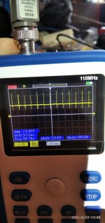
this graph is taken at the Rectifiers
it looks like its turning on then off and trying again
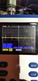
this one is taken at the Gate
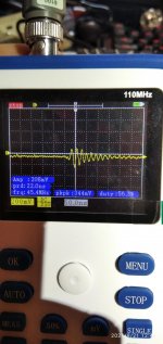
and this one is at the drain
so i took the irf3205 out and tested them with my chinese transistor tester
all of them look good
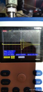
i removed the rectifiers and turned on the amp and this is the waveforms at the rectifier pads without the rectifiers
so i tested the Rectifiers MUR810
and they tested ok
this is at the gates without rectifiers
this one at the drains without rectifiers
so i think the irf3205 are good
the ic sg3525an is good
Resistors are good
heres the waves of the ic sg3525an
the OSC
PIN1
PIN2
Waveform Yotube Video Waveform Yotube Video
SG3525AN PIN VOLTAGES (FAILING) - (WORKING SIDE)
1 2.57 - 1 2.60
2 5.91 - 2 4.32
3 0.018 - 3 0.020
4 0.341 - 4 0.340
5 2.070 - 5 2.077
6 3.75 - 6 3.77
7 2.027 - 7 2.030
8 4.90 - 8 4.92
9 6.42 - 9 5.91
10 0.000 - 10 0.000
11 0.019 - 11 2.073
12 0.000 - 12 0.000
13 6.93 - 13 6.67
14 0.021 - 14 2.071
15 7.58 - 15 7.50
16 5.15 - 16 5.17
the audio output original transistors where the Motorola 2N6490 and 2N6487
i got the Onsemi ones
so no problem with that
replaced the bad and missing .22 ohm 2 watt M.O. Resistors
remember 1 channel still has the originals the one that is ok
when i remove all the new 2n6490 and 2n6487 power supply goes back to normal
i check the 2n6490 and 2n6487 with the transistor tester and they test ok
i always had te amp wired to a OCP OVP power supply setted at 12v and capped at 1 amp and i have 1 car light bulb in series on the positive line
voltage between + and - wires after bulb 8.15v
all opamps has their +15-15v
it is posible to still damage a part with this setup?
help im stuck
An externally hosted image should be here but it was not working when we last tested it.
and i got a problem with the power supply maybe it isnt the power supply
It had some 25N05N blown on 1 Channel
An externally hosted image should be here but it was not working when we last tested it.
i replaced all with the ones i tought the specs where closser IRF3205 An externally hosted image should be here but it was not working when we last tested it.
Datasheetit still has the original Resistors 460 ohms and 2.2k ohms i checked them all and they are on tolerance
the other channel is ok with all the older semicounductors but the drivers because i was having DC voltage on the pads of the audio output on both channels (MPSU06 and MPSU56)
An externally hosted image should be here but it was not working when we last tested it.
Datasheet i replaced them by the MJE1530G Datasheet and MJE1531 DatasheetAn externally hosted image should be here but it was not working when we last tested it.
i had to put them backwards and twist the legs of pins 1 and 2 to match the old drivers
An externally hosted image should be here but it was not working when we last tested it.
EBC leg configurationDC on Audio Output pads solved.
An externally hosted image should be here but it was not working when we last tested it.
so i was having problems on the power supply waveform
the top was a little waved so i finished changing capacitors
Changed the ones with the mpsa056 on top of the ic sg3525a
An externally hosted image should be here but it was not working when we last tested it.
Datasheetand got it fixed
An externally hosted image should be here but it was not working when we last tested it.
for short time wave was looking good but suddenly the waveform went to s*h*i*t*this graph is taken at the Rectifiers
An externally hosted image should be here but it was not working when we last tested it.
it looks like its turning on then off and trying again
An externally hosted image should be here but it was not working when we last tested it.
this one is taken at the Gate
An externally hosted image should be here but it was not working when we last tested it.
and this one is at the drain
An externally hosted image should be here but it was not working when we last tested it.
so i took the irf3205 out and tested them with my chinese transistor tester
all of them look good
i removed the rectifiers and turned on the amp and this is the waveforms at the rectifier pads without the rectifiers
An externally hosted image should be here but it was not working when we last tested it.
so i tested the Rectifiers MUR810
An externally hosted image should be here but it was not working when we last tested it.
Datasheetand they tested ok
An externally hosted image should be here but it was not working when we last tested it.
this is at the gates without rectifiers
An externally hosted image should be here but it was not working when we last tested it.
this one at the drains without rectifiers
An externally hosted image should be here but it was not working when we last tested it.
so i think the irf3205 are good
the ic sg3525an is good
Resistors are good
heres the waves of the ic sg3525an
the OSC
An externally hosted image should be here but it was not working when we last tested it.
PIN1
An externally hosted image should be here but it was not working when we last tested it.
PIN2
An externally hosted image should be here but it was not working when we last tested it.
Waveform Yotube Video Waveform Yotube Video
SG3525AN PIN VOLTAGES (FAILING) - (WORKING SIDE)
1 2.57 - 1 2.60
2 5.91 - 2 4.32
3 0.018 - 3 0.020
4 0.341 - 4 0.340
5 2.070 - 5 2.077
6 3.75 - 6 3.77
7 2.027 - 7 2.030
8 4.90 - 8 4.92
9 6.42 - 9 5.91
10 0.000 - 10 0.000
11 0.019 - 11 2.073
12 0.000 - 12 0.000
13 6.93 - 13 6.67
14 0.021 - 14 2.071
15 7.58 - 15 7.50
16 5.15 - 16 5.17
the audio output original transistors where the Motorola 2N6490 and 2N6487
An externally hosted image should be here but it was not working when we last tested it.
Datasheeti got the Onsemi ones
An externally hosted image should be here but it was not working when we last tested it.
so no problem with that
replaced the bad and missing .22 ohm 2 watt M.O. Resistors
remember 1 channel still has the originals the one that is ok
when i remove all the new 2n6490 and 2n6487 power supply goes back to normal
i check the 2n6490 and 2n6487 with the transistor tester and they test ok
i always had te amp wired to a OCP OVP power supply setted at 12v and capped at 1 amp and i have 1 car light bulb in series on the positive line
An externally hosted image should be here but it was not working when we last tested it.
voltage between + and - wires after bulb 8.15v
all opamps has their +15-15v
it is posible to still damage a part with this setup?
help im stuck
How about you click the little red triangle at the bottom left of your post and ask a moderator to move your CAR AUDIO post to the correct CAR AUDIO section...

The original gate resistors won't work with the 3205s.
Are any of the original 25N05 FETs that are still good?
Are any of the original 25N05 FETs that are still good?
The original gate resistors won't work with the 3205s.
Are any of the original 25N05 FETs that are still good?
yes i have 9 originals testing good
yes i have 9 originals testing good
The original gate resistors won't work with the 3205s.
Are any of the original 25N05 FETs that are still good?
i just put 8 25n05e and still the same problem
i tested them on my transistor tester and they tested good
You'll need to post the gate waveform images.
To upload photos click the following:
Go Advanced
Manage Attachments
Browse
Upload
Repeat as necessary
Preview post to see how the post will look.
Click Submit Reply to send it to the forum.
To upload photos click the following:
Go Advanced
Manage Attachments
Browse
Upload
Repeat as necessary
Preview post to see how the post will look.
Click Submit Reply to send it to the forum.
You'll need to post the gate waveform images.
To upload photos click the following:
Go Advanced
Manage Attachments
Browse
Upload
Repeat as necessary
Preview post to see how the post will look.
Click Submit Reply to send it to the forum.
here they are with the 25n05e originals all tested good
left to right drain-gate-gate-rectifier
Attachments
Last edited:
Measure the DC voltage (it will be very low, so measure carefully) across ALL of the emitter resistors. Do any read more than the others?
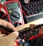
i dont know if im doing it wrong but all of them reads zero
if i put 1 probe on ground and the other on the end of the resistor near the transistor all them read 0.465
if i put 1 probe on ground and the other on the end of the resistor near the transistor all them read 0.465
Last edited:
It looks like it may be going into protection.
If I remember correctly, you stated that the supply worked normally with the rectifiers out of the circuit.
Did you check the small TO-92 transistors in the audio section?
If so, did you check them for open junctions and leakage?
If I remember correctly, you stated that the supply worked normally with the rectifiers out of the circuit.
Did you check the small TO-92 transistors in the audio section?
If so, did you check them for open junctions and leakage?
It looks like it may be going into protection.
If I remember correctly, you stated that the supply worked normally with the rectifiers out of the circuit.
Did you check the small TO-92 transistors in the audio section?
If so, did you check them for open junctions and leakage?
i did but i will doit again
It looks like it may be going into protection.
If I remember correctly, you stated that the supply worked normally with the rectifiers out of the circuit.
Did you check the small TO-92 transistors in the audio section?
If so, did you check them for open junctions and leakage?
all to-92 checks ok maybe the choppers? gona check them now
- Home
- General Interest
- Car Audio
- OLD PPI2300M Restoration problems