Hi Ed!
The General Radio 1585 Sound Level Measuring Set consists of the 1565 Sound Level Meter, the 1562-A Sound Level Calibrator, and set of adapters for 1" and 1/2" microphones.
We had this particular unit manufactured in 1989 calibrated twice I know of through the 1990s and 2000s, and upon return it was always within 1 dB of when we sent it, so I trust it's stability. In addition testing the 1565 with the 1562 show the 1565 to still be in calibration (which they still do) and it is unlikely both would drift the same amount and in the same direction. Bottom line, I believe it is still in calibration.
At one point yesterday, the engineer and studio owner were reconfiguring the API console and switched in a CD which was playing Daft Punk and I saw the GR 1565 register a 108 dB level and higher on peaks for a few seconds before I ran to cover my ears. They seemed unperturbed...which is scary. I have to say the Guzauski-Swist 3Bs sounded fantastic even at that level. Of course the blood pooling in my ears may have muted the sound somewhat...I wish I could afford a pair of them for my shop...but the cobbler's children have no shoes...
All is as it ever was,
Howie
Howie,
Thanks, I only have two of those kits! Never noticed the part number.
As to calibration, I also have a pistonphone, was surplus from NASA.
It is possible I may have accumulated too much gear. But to be honest I like buying, fixing and calibrating the gear.
However my oldest General Radio sound level meter did drift by almost 2 dB from the calibration date of 1955. (2019 test.)
If you want a surprise the meter you have is still in production. The cost is a bit under four grand!
Thought, I post this here, while this is the "sequel" of the Blowtorch threads.
I've tried to build a blowtorch clone, using the info, available in the BT threads.
I'm fully aware that the PSU is NOT real clone, however a 3pin regulator, a shunt and cap multiplier have been used.
Shunt and cap multiplier have been set using a small 4 resistor PCB using a pin header, to replace the original trimmer.
Components used in Line amp:
- 2SK389BL / 2SJ109BL + 2SK214/ 2SJ77
- HOLCO 2H 600R resistors (3 in // to create 200Ohm)
- Takman metalfilm
- Rifa PFE216 polystyrene 100N (as equiv for the relcap's)
- vishay MMB0207 + MBB0207
Power consumption is 40W for the stereo preamp! Yes, about 1/3 of the real BT when the online info is correct. I'm having only 75mA shunt current, but as the idle current througt the 214/77 Fet's is 51mA,with a ripple of about 1mA on max output level in my system, I felt comfortable with the 75mA throught the shunt.
Would this give me 'Roch and roll'?
https://www.diyaudio.com/forums/solid-state/96192-post-solid-pics-714.html#post6708267
We had this particular unit manufactured in 1989 calibrated twice I know of through the 1990s and 2000s, and upon return it was always within 1 dB of when we sent it, so I trust it's stability.
I have a Weston Voltmeter last calibrated 2 days after I was born that you can carefully still parallax view down to better than 3 digits. Some of the more complicated ones like their mechanical power meters look like Swiss watches inside. Got about 50 different ones even a couple from ~1900 from a dumpster at Tufts U. The electrostatic voltmeters are fun in the winter, charge it up with your finger when you get to work and the reading is still there (almost all) at lunch time.
Last edited:
originally posted by Scott Wurcer:
"I have a Weston Voltmeter last calibrated 2 days after I was born that you can carefully still parallax view down to better than 3 digits"
As you know better than I, you can tell precision analog meters by the presence of a mirror at the plane of the scale to allow parallax correction and by the width of the needle over the scales: I'll bet that Weston has less than 0.010" wide needle at that point. Newer, cheaper meters have a big ol' wide needle because the meter accuracy is worse than the width of the needle. Keeping accuracy as the meter orientation is changed requires such a carefully balanced system of intentional forces (springs and magnets) and weights (needle and counterbalances) and natural forces (gravity).
As a kid I learned a lot about how clever analog meter movements are designed by attempting to fix them...although I did successfully rewind at least one Drake transmitter meter which had been toasted by the shunt resistor opening. You ever try to put a new needle on a meter that was hit with an overcurrent strong enough to break the old one off? Good luck. You will find out that needles are made from extremely thin wall hollow tubing like phono styli and finding a suitable replacement is tres difficult. The best I found was a piece of dried straw grass dyed black. Just the microscopic dot of adhesive near the pivot was enough to un-linearize the movement in an uncorrectable way.
I think the decline in availability of precision analog meters was concurrent with the availability of digital displays which we know are perfect , so why bother with a precision analog meter? After all, it is just as easy to gauge trends from a blur of changing digits
  as it is from a moving needle...
I'm going to go remove my tongue from my cheek, have a nice Sunday...
Howie
"I have a Weston Voltmeter last calibrated 2 days after I was born that you can carefully still parallax view down to better than 3 digits"
As you know better than I, you can tell precision analog meters by the presence of a mirror at the plane of the scale to allow parallax correction and by the width of the needle over the scales: I'll bet that Weston has less than 0.010" wide needle at that point. Newer, cheaper meters have a big ol' wide needle because the meter accuracy is worse than the width of the needle. Keeping accuracy as the meter orientation is changed requires such a carefully balanced system of intentional forces (springs and magnets) and weights (needle and counterbalances) and natural forces (gravity).
As a kid I learned a lot about how clever analog meter movements are designed by attempting to fix them...although I did successfully rewind at least one Drake transmitter meter which had been toasted by the shunt resistor opening. You ever try to put a new needle on a meter that was hit with an overcurrent strong enough to break the old one off? Good luck. You will find out that needles are made from extremely thin wall hollow tubing like phono styli and finding a suitable replacement is tres difficult. The best I found was a piece of dried straw grass dyed black. Just the microscopic dot of adhesive near the pivot was enough to un-linearize the movement in an uncorrectable way.
I think the decline in availability of precision analog meters was concurrent with the availability of digital displays which we know are perfect
, so why bother with a precision analog meter? After all, it is just as easy to gauge trends from a blur of changing digits as it is from a moving needle...I'm going to go remove my tongue from my cheek, have a nice Sunday...
Howie
It was certainly "interesting" to follow the different approaches during the stampede to replace those "obsolete" analog VU meters with bar-graph type displays. By then, most of us were so accustomed to the standardized behavior & ballistics of the old meters, it was part of our DNA. But progress marches on; gotta keep fixing what ain't broke.
I think the decline in availability of precision analog meters was concurrent with the availability of digital displays which we know are perfect
Now I'm thinking how far along "digital" has come over the decades. We have gamers bragging about monitors with 120Hz (and higher?) refresh rates, with really high resolution. One could have a smartphone display of an analog meter with realistic resolution and accurate needle ballistics (or faster, your choice) without the processor getting warm.
One would hope a company such as Fluke would do this, but a single prototype would probably only be done for the love of it and only show up on Hackaday. "You can have this too, just download the Github files and ..."
Oh, wait, I bet this is done for the meter movements in those classic compressor plug-ins.
The old Watt-hour meters the electric company used to use are a nice piece of work. Take the voltage, multiply it by the current and integrate over time - all electo-mechanically.
Jeez, I was just thinking the other day about back in the '60s-'70s, when the water meter readers used to have keys to our houses so they could let themselves in once a month to read the meter. And we didn't think twice about it... 😱 😱 😱
Accuphase DG-68 Digital Voicing Equalizer | Stereophile.com
Whilst I can't get my head around a $24k digital EQ esp as it's not clear if it has a digital in/out capability a great shout out to Demian for some very wise words.
I think a laptop and Roon convolution can do all this for $23000 less though.
Whilst I can't get my head around a $24k digital EQ esp as it's not clear if it has a digital in/out capability a great shout out to Demian for some very wise words.
I think a laptop and Roon convolution can do all this for $23000 less though.
I like how the review mentions the "supplied stylus" to create your own response curves. How gracious of them to include this 50-cent dingus at no additional cost! Now all you need to do is crawl up to your equipment rack on your hands & knees to actually draw on the front panel of the stupid thing, since the display is not removable, nor is this functionality duplicated on the cheesy little supplied remote.
I see no mention of any sort of time-domain / impulse-response awareness; nothing about averaging multiple measurements...This appears to be nothing more than ridiculously fancy 80-band digital graphic EQ. For twenty-four thousand bucks, it deserves nothing but scorn and derision - plus maybe an "honorable" mention over in the snake-oil thread. 😡
I see no mention of any sort of time-domain / impulse-response awareness; nothing about averaging multiple measurements...This appears to be nothing more than ridiculously fancy 80-band digital graphic EQ. For twenty-four thousand bucks, it deserves nothing but scorn and derision - plus maybe an "honorable" mention over in the snake-oil thread. 😡
Last edited:
Cost of good ADC/DAC designs would add something to the price of that thing. Also, perhaps good to recall that due to low sales volumes in the high end market, retail prices have to be about 6 times the incremental cost of making one unit (which is higher than the typical 3-5 times markup in high volume consumer markets). Add the cost of milled aluminum panels, custom made metal knobs and feet, etc. It gets expensive when its all added up.
so don't put an ADC/DAC in it? Punters have a DAC already and if they have a digital source it's an unneeded conversion step.
But needed for those who are in business.it's an unneeded conversion step.

Happy weekend everyone!
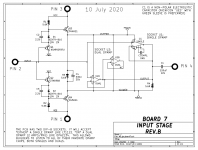
I am making up some buffers for studio signal distribution, and although I trust the isolation and common-mode performance of a high-quality transformer they ain't cheap! As a result I was going to initially look at Bill Whitlock's THAT 1200 series, but I've never designed them into anything. Anyone have experience with them?
Also, I am a fan of JFET front-ends and wanted to know people's experience with the TI OPA164x SoundPlus JFET opamps which can run from +/-18V happily. On paper they look quote good for unity to gain of 10 buffers, are they quirky to implement? John being our resident JFET expert, do you have any experience with them? I do not have a supply of the unobtanium discrete JFETs...
Cheers!
Howie
I would rather quote Scott or Syn08 as Fet experts.
But these perfect TI amps are completely troublefree and easy to use.
Hans
But these perfect TI amps are completely troublefree and easy to use.
Hans
Last edited:
Howie,
I have used a few reels of TI opamps so far without any problems.
I have standardized on a Triad TY-146 150-150/150-150 transformer. I used to use the J’s but these seem quite reasonable in the lots of 100 that I order. PM me an address and I can send you a sample as you have been quite helpful in the past. There are now 2 NPR stations with a full set of transmitter spares at a very low cost!
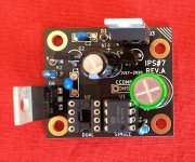
Lots of us are very happy with the OPA134 JFET input opamp from Burr Brown / TI, in unity gain buffers like the one shown below. Looky at the photo, it's an OPA134. Datahseet max supply is 36V, but the strappy bootie circuits limit it to around 20V in this particular board.
For maximum DIY pleasure, the board has two DIP sockets, one to accommodate single-opamp-per-package parts, and another for dual opamps. Now you can try out parts that are ONLY offered as singles (e.g. LT1122), and you can also try out parts that are only offered as duals (e.g. OPA1656). Unlimited freedom for your audiophilia nervosa.
And if you buy ten bucks worth of DIP adapters like these, you can also try out both SMD and THT opamp devices. The fun just never stops.
_
Attachments
- Home
- Member Areas
- The Lounge
- The Black Hole......