Hi all, I have a pretty good collection of 809 tubes that I want to make a class A2 PP amp. Does anyone have a good schematic?
The 809 Triode is primarily designed for RF circuits.
The Mu is 55 (u = 55), and so the plate resistance, rp will probably be very high.
High rp, and a high Q RF resonator work together real well.
High rp, and an audio application, usually requires a very high plate to plate impedance.
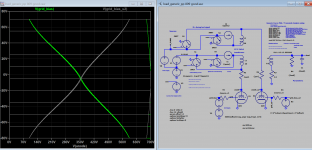
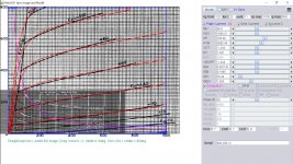
You might want to get the triode curves, and plot a load line before deciding if you will use those tubes that way.
The Mu is 55 (u = 55), and so the plate resistance, rp will probably be very high.
High rp, and a high Q RF resonator work together real well.
High rp, and an audio application, usually requires a very high plate to plate impedance.
You might want to get the triode curves, and plot a load line before deciding if you will use those tubes that way.
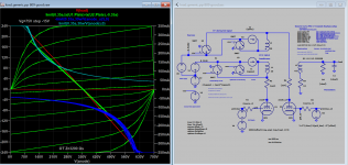
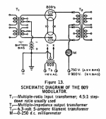
There is only one pp schematic on the net which is a modulator. After some researches and build model for 809, I come up up with these data:
OT 3200:8 (or double this if anode supply 700V)
bias -5
quiescent current 60mA
anode suppy 350V
grid swing +-75
output power 30W rms
Thd 3%
It is found that least distortion around zero bias (-5V), power is increased with higher anode supply but distortion also increased to >5% as grid swing beyond +-75V.
809 model:
Code:
* Created on 08/13/2021 11:38 using paint_kit.jar 3.1
* [URL="http://www.dmitrynizh.com/tubeparams_image.htm"]Model Paint Tools: Trace Tube Parameters over Plate Curves, Interactively[/URL]
* Plate Curves image file: 809.png
* Data source link:
*----------------------------------------------------------------------------------
.SUBCKT 809 1 2 3 ; Plate Grid Cathode
+ PARAMS: CCG=5.7P  CGP=6.7P CCP=0.9P
+ MU=48.5 KG1=1869.51 KP=185.09 KVB=3885.44 VCT=-1.344 EX=1.391
+ VGOFF=-1.344 IGA=0.001161 IGB=0.1405 IGC=29.44 IGEX=1.593
* Vp_MAX=1000 Ip_MAX=800 Vg_step=20 Vg_start=120 Vg_count=11
* Rp=4000 Vg_ac=55 P_max=30 Vg_qui=-48 Vp_qui=300
* X_MIN=35 Y_MIN=7 X_SIZE=692 Y_SIZE=557 FSZ_X=1296 FSZ_Y=736 XYGrid=false
* showLoadLine=n showIp=y isDHT=n isPP=n isAsymPP=n showDissipLimit=y
* showIg1=y gridLevel2=y isInputSnapped=n
* XYProjections=n harmonicPlot=n dissipPlot=n
*----------------------------------------------------------------------------------
E1 7 0 VALUE={V(1,3)/KP*LOG(1+EXP(KP*(1/MU+(VCT+V(2,3))/SQRT(KVB+V(1,3)*V(1,3)))))}
RE1 7 0 1G  ; TO AVOID FLOATING NODES
G1 1 3 VALUE={(PWR(V(7),EX)+PWRS(V(7),EX))/KG1}
RCP 1 3 1G   ; TO AVOID FLOATING NODES
C1 2 3 {CCG} ; CATHODE-GRID
C2 2 1 {CGP} ; GRID=PLATE
C3 1 3 {CCP} ; CATHODE-PLATE
RE2 2 0 1G
EGC 8 0 VALUE={V(2,3)-VGOFF} ; POSITIVE GRID THRESHOLD
GG 2 3 VALUE={(IGA+IGB/(IGC+V(1,3)))*(MU/KG1)*(PWR(V(8),IGEX)+PWRS(V(8),IGEX))}
.ENDS
*$
Attachments
Last edited:
I think I will just use an 811a schematic and dial it down slightly. I do have a few 809 se schematics that I could possibly convert to pp with a decent phase splitter. I would make an 811a amp, but they are getting pricey!
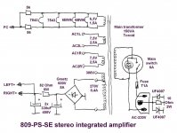
I found this one on a Japanese website, dont have any 6EW7, will probably use something with a plate cap like 807 for the positive grid bias. There was gentleman on here called "multi" who passed away who was a fan of this tube, I wish I could have talked to him.
Attachments

Last edited:
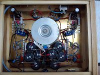
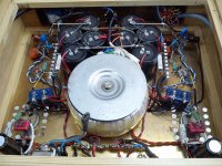
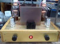
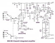
Back in 2013, I made an 809 SE-amplifier in class A2 with a tube, but the connection is also applicable for an push-pull amplifier with the necessary modifications.
Attachments
Last edited:
So I was thinking about using the above schematic (6EW7), but using an interstage TX for the phase splitter. Any issues with having the interstage TX in the GNFB loop? Also not sure if I like the 12au7 input.
Last edited:
Back in 2013, I made an 809 SE-amplifier in class A2 with a tube, but the connection is also applicable for an push-pull amplifier with the necessary modifications
The 680K resistor on the 6AU6 screen needs to be bypassed to the cathode.🙂
The 680K resistor on the 6AU6 screen needs to be bypassed to the cathode.🙂
Attachments
Last edited:
...The 680K resistor on the 6AU6 screen needs to be bypassed to the cathode.🙂
Yes, there is a capacitor between G2 and the cathode of the tube 7543 (6AU6) of 0.22uF / 400V, but I forgot to draw it on the diagram!
Back in 2013, I made an 809 SE-amplifier in class A2 with a tube, but the connection is also applicable for an push-pull amplifier with the necessary modifications.
Hello davorin,
I'm trying to understand the way the 6BW6 is driving the 809. What is the voltage on the grid of the 809 without signal? Am I correct in thinking that the grid of the 809 never goes negative with respect to ground since the cathode of the 6BW6 can't go negative with respect to ground?
On the grid of the tube 809 there is a permanent positive voltage of + 19-20V without signal, and for full excitation it is necessary in this case ~ 12Vrms so that the potential of the grid is always positive.
So still trying to get everything together for this project. I need to order some 6v toroids for the filament from Antek. I think I am going to use AC for the filaments since this will be a push pull amp. I am really feeling a interstage TX for the phase splitter. Got a pair from Electraprint that I would love to use in this amp.
- Home
- Amplifiers
- Tubes / Valves
- 809 PP Schematic Needed