Hello!
I am a beginner in electronics, I have copied some effect pedals and made some diy stuff for me and my friends. I want to make this preamp:
100W Guitar Amplifier (Mk II)
It says that it needs a transformer +/-35V and I have a transformer from M-audio AV40. I don't really know it's specs. Will it work? How can I find the output ac voltage? it's model is BDT-57A676.
Thanks in advance!
Are you making the preamp, or the power amp, or both?
Depending on this answer, you will need different solution as far as transformer/PSU is concerned.
Judging from the photo of this transformer, the number '40' refers to the power: 40W.
If that's correct - 40W transformer can't be used for power amp with rated power of 100W.
This transformer is most likely 2x14V AC.
The best way to check - plug it in to the mains (carefully!) , and measure the AC voltages.
All the information I google about that transformer says it is 14Vac x 2, which will provide you about +/-18Vdc after rectification, which is likely 15-20watts of power from a Class AB amplifier circuit.
This might work for that amplifier, but can't guarantee - You would usually look for a transformer with dual secondary voltages of 20-24Vac and 250-300VA(watt) for a stereo amplifier build. This would provide you +/-28-34Vdc after rectification.
You could build the amplifier and try it with your transformer and if it doesn't provide you enough volume (or work at all), you could upgrade the transformer at that point.
Yes, the original AV40 Studio Monitor has a 2 x 20W@4 ohm power amp, think 2 x TDA2030 or LM1875 class amps.
You can make a nice 15/20W Guitar amp , but falls short for the Rodd Elliott 100W one.
I suggest you build the Rodd Elliott preamp, which works very well, and get a power amp like mentioned above, not a bad starter project at all.
To simplify your life with the "mechanical" part,meaning chassis, cabinet and speaker, you might buy (cheap) a dead/damaged "15-20W practice amplifier" , gut it, meaning tyou empty the chassis, and build your own inside.
Then you can concentrate on the "electronic" aspect, and don´t worry about building the cabinet, cutting/punching sheet metal, getting a "guitar" speaker, etc.
Add a rectifier bridge and two 1000.0x25v capacitors.Suitable for a preamp.
Please Note: PCBs are available for both power amp and preamp.
Last edited:
Are you making the preamp, or the power amp, or both?
Depending on this answer, you will need different solution as far as transformer/PSU is concerned.
You could build the amplifier and try it with your transformer and if it doesn't provide you enough volume (or work at all), you could upgrade the transformer at that point.
I suggest you build the Rodd Elliott preamp, which works very well, and get a power amp like mentioned above, not a bad starter project at all.
To simplify your life with the "mechanical" part,meaning chassis, cabinet and speaker, you might buy (cheap) a dead/damaged "15-20W practice amplifier" , gut it, meaning tyou empty the chassis, and build your own inside.
Then you can concentrate on the "electronic" aspect, and don´t worry about building the cabinet, cutting/punching sheet metal, getting a "guitar" speaker, etc.
Those posts were really helpful. I will give you full info of what I am willing to do.
A friend of mine gave me a broken marshall mg 30 fx. Its power amp and transformer work fine based on my tests. The preamp was damaged and I was willing to build a new one and connect it to the power amp. The biggest problem I am facing is how to give power to the preamp and how to connect the output of the preamp to the power amp as the pcb of the power amp is compact and contains a lot of useless things (as mp3 input etc.).
I chose this preamp because I had all the components. Is there a way to test this preamp in a breadboard? I mean there is not a lot of amps passing through it but the idea of connecting the transformer to the breadboard is kind of scary 😛
Cool.broken marshall mg 30 fx. Its power amp and transformer work fine based on my tests. The preamp was damaged and I was willing to build a new one and connect it to the power amp
I´ll post the current schematic which is available in the Net, you post a couple pucturesshowing the full chassis guts and a couple closeups showing PCB and pots.
*Maybe* you can cut the preamp off with a chainsaw :

he he, just kidding 😉 , perhaps there are separate preamp and power amp boards , that would make your job easier; if "all in one" PCB you may remove it, and build new preamp (Elliott) and power amp, basically reusing "cannibalizing" many parts (rectifiers, filter caps, etc.) from the old one.
You can protoboard Preamp, it´s easy to get +/- 15V from current supply, also finding power amp input., we need to see what you have to be more precise.
So in a nutshell:
* for now leave and use supply and power amp as-is, since they work.
* protobard Elliot preamp, feed it from and use Marshall working elements.
* whenyou are happy with results, instead of designing a board from scratch and ordering it from China, order it from Elliott himself.
Probably a couple Euro extra but you save a ton of work, it´s guaranteed to work properly and it´s a fair contribution to his design.
You might even order and build his power amp PCB too, it will work with currentbtransformer (might need a little touch up) and of course will still put out 30W (whatever the supply allows).
BUT: someday you add the proper supply and you will have those loud 100W available.
beauty is that you can go step by step, at your own pace.
As Juan Manuel wrote above, most likely you don't need new transformer.
Very likely you can use existing transformer, or even whole PSU already supplied with the power amp.
Very likely you can use existing transformer, or even whole PSU already supplied with the power amp.
That's exactly what I am planning to do. My only problem is the step by step approach.Cool.
he he, just kidding 😉 , perhaps there are separate preamp and power amp boards , that would make your job easier; if "all in one" PCB you may remove it, and build new preamp (Elliott) and power amp, basically reusing "cannibalizing" many parts (rectifiers, filter caps, etc.) from the old one.
1st step: Build the preamp. How can I know that it is working? How can I test it? I am used to test my pedals in a breadboard (but this only demands 9v dc)
connect them to my amp and if its working next step is building it in a veroboard or a diy PCB.
Can I use the lm386 chip to make a small power amp just to see if the preamp is working fine? Would this be possible?
2nd Step: Removing the important parts from the Power amp pcb and rebuilding it to a new pcb. The problem here is that I don't know which parts are necessary. I can recognize the amplifier chip, the 4 diodes creating the rectifier and the caps after that. (I will sent some pictures of what I have in hand).
A thought I had is that if I can detect the pins for preamp input I can skip the part of scrapping.
whenyou are happy with results, instead of designing a board from scratch and ordering it from China, order it from Elliott himself.
Ordering the pcbs from Elliot will cost me 150 euroes (I am from greece)... That's exactly the cost of a new marshall amp I am trying to fix.
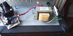
And some pictures of the "patient"
Attachments
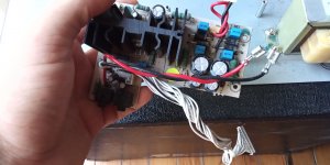
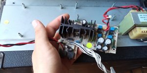
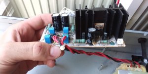
This is a power amplifier using IC (TDA2030 or 2050?). The PCB has a rectifier to power the power amplifier. A preamplifier can work from it.
Last edited:
This is a power amplifier using IC (TDA2030 or 2050?). The PCB has a rectifier to power the power amplifier. A preamplifier can work from it.
It's a TDA 2050.
Hey! You have 90% of your problem solved!!!
You have chassis, cabinet, speaker, power transformer, power supply (both working as you say), you only need to make the preamp.
That PCB certainly has +/-15V OUT to feed former preamp, fine for the new one, and a Power Amp signal input .
So reassemble it, connect speaker and turn it ON, it apparently works, if one of those mini jacks is the CD player input, connect a Phone or Player and test it works.
Here is the full amplifier schematic:

Just in case, download it to your own PC, because if Imgur drops it, it will disappear here too.
Left side (on schematic, not necessarily on PCB) seems to be the signal IN, follow its tracks, one "should" lead to one pin in that long white connector.
You should also find there +/-15V sources, and of course Ground.
What OldDIY says, of course, he´s an *experienced* builder and Tech.
Yes, it´s a TDA2050, obviously original.
Pamper it because today they are all FAKES.
In the long run, download some simple free PCB design software and learn to use it, but too much for the *first* project.
My suggestion was because *some* amps (Fender) use a huge wall to wall PCB which must be discarded to fit anything else.
In that case, recycling diodes, filter caps, maybe a couple Zeners, can save some $$$$, not needed here.
Then compare PCB and print and mark interesting points with very fine tip permanent marker.
I am in Argentina, same "rest of the World" area as Greece, we pay tons of postage, have lazy/cheating Customs, the works, but even so was amazed at your quote.
Rodd claims $30 for postage (fixed prize), U$26 for power amp PCB and U$18 for Preamp, a grand total of U$74 (which is a lot on its own) but nowhere near 150 Euro 😱
A couple PCBs in a padded envelope generally do NOT pay any Customs Tariff and are delivered at home by regular Mail, but hey, I might learn something new.
You can design a proper Veroboard layout in a couple afternoons with just some pencil, graph/grid paper
and, most important, an eraser he he, you will redo paths and tracks many times, but it´s fun and cheap.
In the old days there was a wonderful, very practical british invention: "the blob", it was a matching couple of 1 protobord and 3 "veroboards", exact same size and pattern.
Once you were happy with a design, you transferred parts and wires one by one to a real copper and pertinax PCB where of course you soldered them.
Very error proof and practical.
Today Adafruit does something similar:

Tracks are very narrow on purpose, so they are easy to remove when/if neded:


You may use your own Protoboard and order the 3 "vero" pack only when needed.
A VERY clever and practical idea for Hobbyists.
You have chassis, cabinet, speaker, power transformer, power supply (both working as you say), you only need to make the preamp.
That PCB certainly has +/-15V OUT to feed former preamp, fine for the new one, and a Power Amp signal input .
So reassemble it, connect speaker and turn it ON, it apparently works, if one of those mini jacks is the CD player input, connect a Phone or Player and test it works.
Here is the full amplifier schematic:
Just in case, download it to your own PC, because if Imgur drops it, it will disappear here too.
Left side (on schematic, not necessarily on PCB) seems to be the signal IN, follow its tracks, one "should" lead to one pin in that long white connector.
You should also find there +/-15V sources, and of course Ground.
What OldDIY says, of course, he´s an *experienced* builder and Tech.
Yes, it´s a TDA2050, obviously original.
Pamper it because today they are all FAKES.
Use the existing amp and supply.1st step: Build the preamp. How can I know that it is working? How can I test it? I am used to test my pedals in a breadboard (but this only demands 9v dc)
You will first protoboard it, then transfer it to a more stable veroboard which is fine for a first project.connect them to my amp and if its working next step is building it in a veroboard or a diy PCB.
In the long run, download some simple free PCB design software and learn to use it, but too much for the *first* project.
You can, but no need to, just use the Marshall one.Can I use the lm386 chip to make a small power amp just to see if the preamp is working fine? Would this be possible?
Happily no need to, since they are working and on their own not-too-large PCB2nd Step: Removing the important parts from the Power amp pcb and rebuilding it to a new pcb. The problem here is that I don't know which parts are necessary. I can recognize the amplifier chip, the 4 diodes creating the rectifier and the caps after that. (I will sent some pictures of what I have in hand).
My suggestion was because *some* amps (Fender) use a huge wall to wall PCB which must be discarded to fit anything else.
In that case, recycling diodes, filter caps, maybe a couple Zeners, can save some $$$$, not needed here.
Print schematic in a large piece of paper, minimum A4 and if possible A3 (at some priting shop) or half and half on two A4 and tape them together.A thought I had is that if I can detect the pins for preamp input I can skip the part of scrapping.
Then compare PCB and print and mark interesting points with very fine tip permanent marker.
Ouch!Quote:
Originally Posted by JMFahey View Post
whenyou are happy with results, instead of designing a board from scratch and ordering it from China, order it from Elliott himself.
Ordering the pcbs from Elliot will cost me 150 euroes (I am from greece)... That's exactly the cost of a new marshall amp I am trying to fix.
I am in Argentina, same "rest of the World" area as Greece, we pay tons of postage, have lazy/cheating Customs, the works, but even so was amazed at your quote.
Rodd claims $30 for postage (fixed prize), U$26 for power amp PCB and U$18 for Preamp, a grand total of U$74 (which is a lot on its own) but nowhere near 150 Euro 😱
A couple PCBs in a padded envelope generally do NOT pay any Customs Tariff and are delivered at home by regular Mail, but hey, I might learn something new.
You can design a proper Veroboard layout in a couple afternoons with just some pencil, graph/grid paper
and, most important, an eraser he he, you will redo paths and tracks many times, but it´s fun and cheap.
In the old days there was a wonderful, very practical british invention: "the blob", it was a matching couple of 1 protobord and 3 "veroboards", exact same size and pattern.
Once you were happy with a design, you transferred parts and wires one by one to a real copper and pertinax PCB where of course you soldered them.
Very error proof and practical.
Today Adafruit does something similar:
Tracks are very narrow on purpose, so they are easy to remove when/if neded:
You may use your own Protoboard and order the 3 "vero" pack only when needed.
A VERY clever and practical idea for Hobbyists.
Last edited:
Connect the transformer to the mains through a 40-60 W incandescent lamp connected in series (check the correspondence of the mains voltage and the transformer).
Measure the voltage on the power supply rails of the amplifier (approximately + -23V) relative to the common rail (ground).
Measure the voltage at the IC output (0 V relative to ground).
Connect a repair speaker to the output (any that you do not mind). Input the amplifier with an audio signal from a CD or DVD.
There should be sound when connected correctly. Otherwise, the IC is faulty and requires replacement.
Last edited:
Hey! You have 90% of your problem solved!!!
You have chassis, cabinet, speaker, power transformer, power supply (both working as you say), you only need to make the preamp.
In the long run, download some simple free PCB design software and learn to use it, but too much for the *first* project.
Ι have made a pcb sketch in KiCad. It's my first sketch so it might be sloppy.
So reassemble it, connect speaker and turn it ON, it apparently works, if one of those mini jacks is the CD player input, connect a Phone or Player and test it works.
I tried it but I think I made a short and blew a diode. If I am not mistaken is the 1 watt 15V zener diode. I replaced it and something strange is happening. The diode I replaced has 15V when I measure it. But the other zener diode has -8V. Shall I just replace the diode? or there is a chance that something else is going wrong?
(in the schematic they are placed in bottom left and named zd1 and zd2)
And if I am not mistaken (once more 😛 ) I won't need the power section of the preamplifier from the Elliot design. (I am reffering to D5, D6, C12, C13, R19 and R20 from figure 1 in Elliots schematic for the preamp).
I found those pins following the tracks of the power amp pcb!Left side (on schematic, not necessarily on PCB) seems to be the signal IN, follow its tracks, one "should" lead to one pin in that long white connector.
You should also find there +/-15V sources, and of course Ground.
What OldDIY says, of course, he´s an *experienced* builder and Tech.
Yes, it´s a TDA2050, obviously original.
Pamper it because today they are all FAKES.
I didn't understand what I must do 😛
Use the existing amp and supply.
I think that this is a little dangerous. The only thing I can do is to take the ground 15/-15V tracks and solder some long cables and connect them to the breadboard. A slight movement can cause a short.
Rodd claims $30 for postage (fixed prize), U$26 for power amp PCB and U$18 for Preamp, a grand total of U$74 (which is a lot on its own) but nowhere near 150 Euro 😱
Here is were I am mistaken 😛. I am willing to donate if my project works. I don't care to keep the money if I fix the amp so I can sent him whatever amount my friend will give me. I think it's kind of fair.
Today Adafruit does something similar
I had no Idea this existed! I will probably need this in the future as the most boring part for me is to etch pcb or thinking about the transfer to a veroboard!!
Thank you very much for your time! I honestly appreciate the work you put in this post!
Attachments

Connect the transformer to the mains through a 40-60 W incandescent lamp connected in series (check the correspondence of the mains voltage and the transformer).
Measure the voltage on the power supply rails of the amplifier (approximately + -23V) relative to the common rail (ground).
Measure the voltage at the IC output (0 V relative to ground).
Connect a repair speaker to the output (any that you do not mind). Input the amplifier with an audio signal from a CD or DVD.
There should be sound when connected correctly. Otherwise, the IC is faulty and requires replacement.
I connected my phone and no sound was coming out. So This means power amp chip is dead?
- Home
- Amplifiers
- Solid State
- Rod Elliot preamp 100 watt