The two switches are one DPDT switch. Also the input voltage is reversed. I will issue corrected and clarified copy after a bit.
The typo okay, but last night I looked at your pdf, and even with my limited knowledge, I concluded it was not two switches.
You specified a DPDT and the only reason for that would be for the two marked on the schematic as SPST x 2 = 1 DPDT.
Anyway, congrats to all the greedy boys/girls who won the last round. I'm happy for you all... no really I am, okay maybe not happy, but glad, yes glad that's it.... well maybe not glad... Okay, stay away from freezers and backhoes for the next little while. 😛
😛
(Lest anyone take that seriously, I am happy for you all and wish you no ill will) mostly 😛
JT
You specified a DPDT and the only reason for that would be for the two marked on the schematic as SPST x 2 = 1 DPDT.
Anyway, congrats to all the greedy boys/girls who won the last round. I'm happy for you all... no really I am, okay maybe not happy, but glad, yes glad that's it.... well maybe not glad... Okay, stay away from freezers and backhoes for the next little while.
😛(Lest anyone take that seriously, I am happy for you all and wish you no ill will) mostly 😛
JT
Last edited:
For the Europeans:
DPST switch that fits the cut-out in the back panel:
%product-title% kaufen
10A AC rating, no DC rating, but seems to be the same series as the SPST switch provided in my kit. 😉
Regards, Claas
DPST switch that fits the cut-out in the back panel:
%product-title% kaufen
10A AC rating, no DC rating, but seems to be the same series as the SPST switch provided in my kit. 😉
Regards, Claas
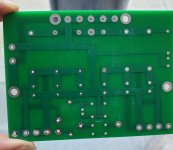
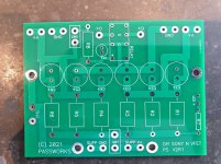
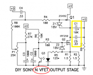
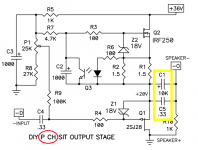
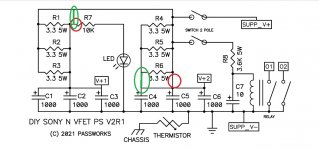
I received a PM from a member regarding the N Vfet PS filter as he might want to use it for his ACA/ P VFET. Others might be tempted as well, so here below some pics:


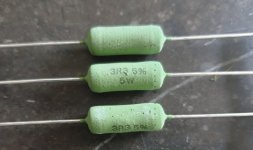
and yes the resistors are 5 w:

I guess it would not be too difficult to do on a perfboard.
and yes the resistors are 5 w:
I guess it would not be too difficult to do on a perfboard.
Attachments
Last edited:
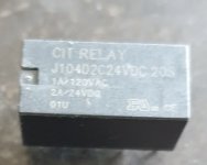
Ralays for cars (coils of 14V) have DC contacts that have a large area of contact and are designed to limit DC arcing; that is opposed to standard relay AC contacts that are round and designd to suppress a AC arc.
I have a relay that turns. That is also great for DC I think.
I have a relay that turns. That is also great for DC I think.
This PSU board arranges the relay contacts to be in parallel with the loudspeaker. While the supply voltage is ramping up (@ power-on) or ramping down (@ power-off), Nelson's circuit closes the relay contacts. This means the loudspeaker(+) terminal is shorted to the loudspeaker(-) terminal in both channels, during power-on and power-off events. And of course the relay contacts are also closed, shorting out the loudspeakers, the whole time the amp is turned off.
The VFET amp channel board is AC coupled to the loudspeaker through a very large electrolytic capacitor on that board. So the signal applied to the loudspeaker is AC (not DC) and the relay contacts are required to switch AC (not DC).
_
The VFET amp channel board is AC coupled to the loudspeaker through a very large electrolytic capacitor on that board. So the signal applied to the loudspeaker is AC (not DC) and the relay contacts are required to switch AC (not DC).
_
Attachments
Last edited:
Pop, I started a thread for the N-Channel build, if you want to keep the two on seperate threads. I know a lot is the same, but it might be helpful.
Use it or not... DIY Sony VFET pt 2 (N-Channel Build)
JT
Use it or not... DIY Sony VFET pt 2 (N-Channel Build)
JT
I am a bit confused about 2 switches (or one switch DPDT as noted on the schematic). In the kit I received there is only one switch and it is SPST. Any idea?
I just received my kit and I can confirm that it’s a SPST that is include in the N vfet kit.
Hubert
Attachments
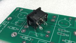
I just received my parts kit. Also confirmed that the shipped switch is SPST. My chassis is vacationing in Paris, so don't have it to double check. I did have some CW GRS-4021 in my parts bin and they are the same dimensions. Good news is that both Mouser (15 variations) and Digi-Key have them in stock in the US.
I just received my parts kit. Also confirmed that the shipped switch is SPST. My chassis is vacationing in Paris, so don't have it to double check. I did have some CW GRS-4021 in my parts bin and they are the same dimensions. Good news is that both Mouser (15 variations) and Digi-Key have them in stock in the US.
Great thank you for the part number that was my next question!
Thanks for proofing the schematics. I'll issue the corrected documents later today.
Attachments
Looks like the correction caused an issue down the line. Also the PS board shows the LED circuit connected directly to the Supply V+.
It's reminiscent of my day job when I designed building structures. Pesky issues would crop up when back-checking structural drawings as changes would affect other parts of the drawing, necessitating more changes.🙂
It's reminiscent of my day job when I designed building structures. Pesky issues would crop up when back-checking structural drawings as changes would affect other parts of the drawing, necessitating more changes.🙂
Attachments
time for assistent/secretary, to ease trivial burden on Creative Spirit
I know perfect candidate, gray beard and still extraordinary handsome

I know perfect candidate, gray beard and still extraordinary handsome
Hmmm... I seem to remember a post with Pop and a guy  , on a boat, who resembles the description... I can't place who else is that Fuglishious?
JT
, on a boat, who resembles the description... I can't place who else is that Fuglishious? JT
Last edited:
no boat involved
that's too much effort for gray bearded ones
everything can be achieved already on shore

that's too much effort for gray bearded ones
everything can be achieved already on shore
- Home
- Amplifiers
- Pass Labs
- DIY Sony VFET pt 1