I agree, yes there is certain level of simplification leading to inaccuracy, but it also offers clear improvement of design analysis over no vertical simulation at all. To measure verticals physically with such a design is not an easy task.
XYZ drivers coordinates are used to compute the result for mic location in VituixCAD, but it also enables vertical culculations (Prefernces/Include verticals... checkbox).
XYZ drivers coordinates are used to compute the result for mic location in VituixCAD, but it also enables vertical culculations (Prefernces/Include verticals... checkbox).
So the "heatmap" shows the horizontal dispersion? Why is there a notch at 2 kHz, which is not apparent in the indivjdual off-axis measurement curves? This does not see right to me.I took horizontal measurements 0-90deg, in 10deg steps. Vertical measurements are not needed with Vituix v2.
Also, to get the power response right, you'll need full 360° measurements, both horizontal and vertical.
Polar map shows VERTICAL. I explained in my previous posts from today. This is the feature of Vituix.
About power response, I am aware of that. Full measurements are needed to get overall power response tilt right. I am also interested in overall smothness, and the slope without dips and peaks. Overall sound balance has to be assessed and adjusted by the listening.
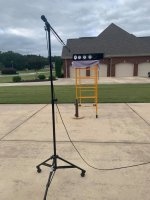
I plan to make new measurements in larger space to achieve longer window, so I will make full 360deg measurement horizontal.
About power response, I am aware of that. Full measurements are needed to get overall power response tilt right. I am also interested in overall smothness, and the slope without dips and peaks. Overall sound balance has to be assessed and adjusted by the listening.
I plan to make new measurements in larger space to achieve longer window, so I will make full 360deg measurement horizontal.
So the "heatmap" shows the horizontal dispersion? Why is there a notch at 2 kHz, which is not apparent in the indivjdual off-axis measurement curves? This does not see right to me.
Also, to get the power response right, you'll need full 360° measurements, both horizontal and vertical.
The heatmap shows vertical dispersion calculated with horizontal responses. As if you loaded horizontal responses as vertical in VCad . When you enter physical alignment of drivers, the software calculates nulls as they are products of centers distance and phase relations between transducers. So, while it doesn't provide utmodt precision, nulls are at the right places but would probably look somewhat different because of different diffraction signature for the same driver measured vertically.
Last edited:
Yeah, Vituix likes to do this kind of guesswork... I prefer rsults based on proper measurements.
This kind of guesswork is not far from reality and is still better that no verticals or just sims based on ideal driver models or traced factory graphs.
We all know what would be ideal and how it all should be done, but then....reality comes. Vertical measurements of such a heavy floorstander is work for two pairs of hands. Moreover my turntable is 1m diameter, stable stand would be needed to prevent loudspeaker from falling down or tipping over. I do not mean it as excuses, I am just not convinced it is worth it.
One can do good sounding speaker even without verticals. With non-coicident drivers there vertical off-axis dips will still exist, and we could endlessly discuss if this bad or that bad is better.

Big speakers are pain in the butt 🙂 i managed to do it like so: found a trolley from hospital dumpster (food serving trolley). Cut it to proper height and made a table top out of it. Then, make somekind of pivot pin and attach it to the trolly. I used a long threaded rod as a pivot pin. Tape driver cut out to the floor and draw the angles to it, put the trolly over and attach the pivot pin to center. make a pointer out of chopsticks or what ever to point the 0 degrees 😀 strap the speaker on with ratchetstraps and start the process. takes ages, but full 360 verticals no problem 🙂
one doesn have to move the speaker on the trolley when doing like this. just move the location of the pivot pin for each driver. wheels under the trolly allow the system to turn around any pivot point. It is not millimeter tolerance setup, but got the work done well enough.
one doesn have to move the speaker on the trolley when doing like this. just move the location of the pivot pin for each driver. wheels under the trolly allow the system to turn around any pivot point. It is not millimeter tolerance setup, but got the work done well enough.
Last edited:
Hardly seems fair to blame the tool when the operator is completely aware of what they are doing.Yeah, Vituix likes to do this kind of guesswork... I prefer rsults based on proper measurements.
I found this image from Erin Hardison that seems like a safe and not wildly expensive optionBig speakers are pain in the butt 🙂 i managed to do it like so:
Attachments
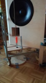
pretty much exactly what i did and tried to explain, thanks for the photo fluid! except on the photo the pivot pin is tied to the leg of the trolly so the speaker needs to be moved on the trolly to the rotation axis for each driver. instead moving the speaker one can move the pivot pin to the driver that is being measured. Maybe he did it like that as well.
edit. found a photo of my jig demonstrating that the pivot pin can be positioned anywhere on the trolly with a bit of thinking and ductape 😀 also, degree pointer thingy visible on the photo for inspiration 😀
edit. found a photo of my jig demonstrating that the pivot pin can be positioned anywhere on the trolly with a bit of thinking and ductape 😀 also, degree pointer thingy visible on the photo for inspiration 😀
Attachments
Last edited:
Fluid, I was thinking of doing something like on the picture, it looks like the easiest way and it offers good stability for speaker placement. It seems one log of that trolley is pivot point.
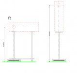
Such a simple solution that I hadn't considered before seeing Erin's picture. The Arta option is easy enough to add to an existing turntable stand and would work much the same.
You live in a very nice place, possibly the cheapest good beer I have ever bought was in Brno 🙂
You live in a very nice place, possibly the cheapest good beer I have ever bought was in Brno 🙂
Attachments

Last edited:
Hi Pida.
Do you have plans to make a 2-way TeXtreme speaker system (TW29TXN-B-8 + MW16TX-8), similar to your JurKo project?
That would be great 🙂
At this video sounds SB TeXtreme speakers.
Buil your own speakers // Sb Acoustics evaluation room /// Munich High End 2019 - YouTube
Do you have plans to make a 2-way TeXtreme speaker system (TW29TXN-B-8 + MW16TX-8), similar to your JurKo project?
That would be great 🙂
At this video sounds SB TeXtreme speakers.
Buil your own speakers // Sb Acoustics evaluation room /// Munich High End 2019 - YouTube
Last edited:
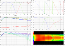
So today I took measurements for crossover design, and modelled the first version. I am very happy with the results so far. And the dip at 13kHz does not look good, but it is only -3dB and very narrow, I will try some experiment to improve that, later, but I assume the dip will not have significant impact on sound quality.
Modelling done in Vituix v2, graphs contain vertical measurements.
Looks very good to me. Even with 0-90 measurements one can tell when the system "locks" nicely. When it's good it's good.
Fluid: beer is not as cheap as used to be but is still very good.
Dreew: no plans for such a project yet but let's wait for MW16TX qualities in Shamal first. I would actually like to build something smaller and simpler again. MW16TX+TW29TXN+Jantzen WG could work well in 2way straight baffle cabinet with symetric LR2, though LR4 usually provides better results when mid and tweeter dispersions are matched at Fc..
Dreew: no plans for such a project yet but let's wait for MW16TX qualities in Shamal first. I would actually like to build something smaller and simpler again. MW16TX+TW29TXN+Jantzen WG could work well in 2way straight baffle cabinet with symetric LR2, though LR4 usually provides better results when mid and tweeter dispersions are matched at Fc..
Last edited:
Good idea.I would actually like to build something smaller and simpler again. MW16TX+TW29TXN+Jantzen WG could work well in 2way straight baffle cabinet with symetric LR2, though LR4 usually provides better results when mid and tweeter dispersions are matched at Fc..
I think that TeXtreme on the tweeter and midwoofer will give a very coherent and smooth sound.
Just out of curiosity I tried to model LR4 between woofer and mid.
Very nice indeed ! If possible with your passive crossover, I would try to add + 1 dB on the T25B in waveguide
I would also consider MW19TX, but P version required larger volume compared to MW16, and did not go lower in bass. In that regard MW16 looked optimal. But for TX versions I would need to make cabinet volume modelling again.
I also realized that LR2 with TX versions is hardly possible.
I also realized that LR2 with TX versions is hardly possible.
Good idea.
I think that TeXtreme on the tweeter and midwoofer will give a very coherent and smooth sound.
I agree. For now I keep it -1dB as T25B without WG required fine tuning in 3-10kHz area, but with WG I expect different sound in that area and it make sense to start with flat.
Very nice indeed ! If possible with your passive crossover, I would try to add + 1 dB on the T25B in waveguide
- Home
- Loudspeakers
- Multi-Way
- New project: 3way 22W/4851, MW16TX-8, T25B in WG